


Most engineers and buyers who search for “reducing CNC machining cost” are not looking for vague tips. They want specific design moves that quickly bring quotes down without killing function or quality. This article focuses exactly on that: how smart design choices cut CNC machining cost in a predictable, repeatable way.
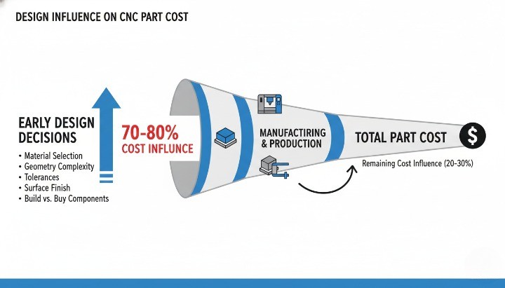
Across manufacturing, research consistently shows that design decisions lock in around 70–80% of a product’s life-cycle cost, long before the first chip is cut.When teams treat cost only as a purchasing problem, they often end up fighting symptoms instead of root causes. By contrast, when engineering and procurement collaborate around design-for-cost from day one, they can remove entire cost drivers instead of bargaining over hourly rates.
In this guide, you will see how CNC costs are actually built up, which design choices drive machining time, and where you can redesign geometry, tolerances, materials, and setups to unlock meaningful savings. The goal is simple: give you practical design levers you can use on the next RFQ, not just theory.
Why Smart Design Is the Fastest Way to Reduce CNC Machining Cost?
Smart design is the fastest way to reduce CNC machining cost because it changes the cost structure before it is “locked in.” Studies on design-to-cost and DFM show that most of a product’s cost is determined during early design, while changes in later stages are far more expensive and disruptive. When you simplify geometry, relax non-critical tolerances, and choose machinable materials up front, you directly reduce machine time, setups, tooling wear, and scrap – the real drivers of CNC pricing.
From a practical point of view, design changes also scale better than negotiation. You can push a supplier to drop their hourly rate once or twice. However, a design that cuts 20–30% of machining time will reduce cost every time the part is ordered, across every supplier you ever work with. That is why the most successful OEMs treat cost reduction as a design discipline, not a purchasing campaign.
At the same time, smart design is not about “cheapening” the part. It is about aligning features and tolerances with actual functional needs. Many CNC parts carry legacy specs that no one questions: tight tolerances on non-critical faces, deep pockets that add stiffness no one uses, or engraving that adds no value. When you systematically remove these hidden cost drivers, you keep performance while stripping out waste.

How Design Decisions Drive Machining Time and Pricing?
CNC pricing is built around machine time, material use, and setup effort. Your drawing and 3D model tell the supplier how much of each they will need to spend. A few design examples make this clear:
-
A simple through-hole that uses a standard drill takes seconds. A deep, non-standard hole with tight tolerance may need step drilling, reaming, or boring.
-
A shallow pocket with generous radii can be milled quickly with a larger tool. A deep pocket with sharp internal corners forces smaller tools, lower feeds, and more passes.
-
A flat surface with standard Ra can be milled in one operation. A cosmetic surface that needs very low roughness may require extra finishing passes or grinding.
Because of these patterns, geometry, tolerances, and surface finish directly translate into cycle time and tooling complexity, which then feed into the machine-hour calculation in almost every CNC shop.
Aligning Engineering and Procurement for Cost-Effective Parts
Engineers tend to optimize for function and reliability. Procurement focuses on price, lead time, and supplier risk. Smart cost reduction happens when both groups look at the same part and ask a shared question: “Which features truly drive function, and which ones just drive cost?”
In practice, that alignment usually includes:
-
Joint reviews of 3D/2D before RFQ, not after you receive expensive quotes.
-
Clear marking of critical-to-function dimensions versus “nice to have” specs.
-
Agreement on which surfaces are cosmetic, which are functional, and which can remain “as machined.”
-
Early discussions about volume, lifetime demand, and whether alternative routes like casting + CNC could make sense later.
When engineering and procurement align this way, suppliers receive RFQs that already reflect sensible cost targets. As a result, quotes come back closer to budget on the first round, and fewer redesign iterations are needed.
Common Design Mistakes That Inflate CNC Costs
Several recurring patterns cause CNC quotes to spike, even when the part looks “simple” on screen. Typical examples include:
-
Over-tight tolerances on non-critical features, forcing slower machining and 100% inspection.
-
Deep, narrow pockets or tall, thin walls that require very conservative cutting parameters.
-
Undercuts and hidden features that need special tools, 5-axis machining, or extra setups.
-
Multiple surface finishes on the same part, increasing handling and process steps.
-
Text, logos, and decorative chamfers that add time but not value.
These are not minor issues. Each one increases setup time, tool changes, NC programming complexity, or QA workload. Multiply this across thousands of parts, and you can easily add double-digit percentages to your CNC spend. Systematically hunting down and removing these design traps is often the single biggest lever you have.
How CNC Machining Cost Is Actually Calculated?
CNC machining cost is usually calculated by combining direct material, machine time and labor, and manufacturing overhead into a total unit price. Standard manufacturing cost frameworks describe this as direct materials + direct labor + manufacturing overhead, and CNC shops typically follow the same logic when they estimate part cost. For many factories today, direct materials alone can account for roughly 50–70% of production cost, with the rest coming from labor and overhead.Your design influences all three components, which is why design-driven cost reduction is so powerful.
For engineers and buyers, it is useful to think about CNC pricing not as a “black box quote,” but as the sum of several transparent building blocks: raw stock and scrap, cutting time, setup and programming, quality control, and a share of plant overhead. Once you see the logic, you can design parts and RFQs that pull those levers in your favor.
Main Cost Components — Machine Time, Material, Setup, QA, Overhead
Most CNC shops, whether in China, Europe, or the US, build part prices from a similar structure:
| Cost Component | What It Typically Includes | Key Design Levers |
|---|---|---|
| Material and Blank | Raw stock, cutting to size, scrap, and yield | Overall size, shape, material grade, blank optimization |
| Machine Time and Labor | Cutting time, tool changes, operator supervision, NC program run time | Geometry complexity, feature count, tolerances, tool access |
| Setup and Programming | CAM programming, fixturing, machine setup, first-article tuning | Number of setups, need for custom fixtures, part family reuse |
| Quality and Inspection | Gauging, CMM time, documentation, sampling or 100% checks | Tolerance strategy, datum scheme, number of critical features |
| Overhead and Margin | Machine depreciation, maintenance, shop rent, utilities, management, profit | Order quantity, repeat business, long-term collaboration |
Material and blank cost sit on top of general product cost rules, where direct materials form a major share of manufacturing cost in many industries. Machine time and labor are driven by feeds and speeds, tool paths, and tool changes, which in turn depend on geometry and tolerances. Setup and QA behave more like step costs: you pay them once per batch, so they hurt more when orders are small or highly customized.
From a design perspective, the most attractive savings come from shorter machining cycles, fewer setups, and simpler inspection. These directly reduce the “time under the spindle” and the number of touch points each part needs.
How Quotation Tools and Estimators Use Your 3D/2D Data?
When you send an RFQ with 3D models and 2D drawings, most suppliers follow a hybrid process that combines software and human judgment:
-
They load your 3D model into CAM or cost-estimation software.
-
The software analyzes geometry: bounding box, volumes to remove, hole count, feature depths, and tool access.
-
It suggests estimated cycle times based on default tools, materials, and machine parameters.
-
An estimator or process engineer reviews these results, adjusts speeds and feeds, and decides how many setups are needed.
-
They cross-check drawing tolerances and surface finish notes, then add time for programming, fixturing, and inspection.
-
Finally, they apply their internal machine-hour rate, material pricing, overhead, and margin.
Automated platforms may rely more heavily on algorithms, while traditional shops rely more on human experience. However, in both cases, your model and drawing are the source of truth. If your design implies small tools, deep pockets, multiple orientations, or tight GD&T, the cost engine will automatically push machine time upward.
Because of this, even small updates in your model can have a large impact on the way quotation tools “see” your part. A slightly larger corner radius that allows a bigger end mill, or a reduced pocket depth that improves tool stability, can take minutes off the machining cycle – which is exactly what the cost estimator will register.

Where Smart Design Has the Biggest Leverage on Cost?
Not all design changes are created equal. In practice, several areas consistently deliver the highest return:
-
Geometry simplification: Reducing deep cavities, tall thin walls, undercuts, and tiny features cuts cycle time, improves tool life, and often allows cheaper machines to be used.
-
Tolerance and surface finish strategy: Relaxing non-critical tolerances and avoiding unnecessarily low Ra values reduces both machining and inspection time.
-
Material and blank choices: Selecting alloys with better machinability or resizing the blank to reduce waste can significantly lower material and rough machining cost.
-
Setup minimization: Designing parts so key features are accessible in two setups instead of four can halve setup time and reduce positioning errors.
-
Part family standardization: Using common hole sizes, radii, and wall thicknesses across a product family allows suppliers to reuse tooling, fixtures, and CNC programs.
These design levers work especially well because they attack cost at the point where it is most flexible. Industry research on new product development emphasizes that design decisions in early stages determine the majority of life-cycle cost, while later process improvements offer smaller gains.
For engineering and procurement teams, the practical takeaway is straightforward: if you want durable CNC cost reduction, start by redesigning parts for manufacturability, then let purchasing optimize commercial terms on top of that.
The Core Cost Drivers in CNC Machining
CNC machining cost is determined by several major drivers that influence machine time, setup effort, material usage, and inspection workload. When you understand how each driver behaves, you can design parts that reduce cost before machining begins. The five core cost drivers are geometry complexity, material and stock selection, tolerance and surface finish requirements, setup and fixturing, and quantity or order pattern. Each one interacts with your 3D model and drawing in a predictable way, which gives you clear levers for cost reduction.

Geometry Complexity and Feature Count
Geometry complexity is one of the strongest predictors of CNC machining cost. Complex designs often require smaller tools, slower feeds, deeper cuts, or multiple toolpaths, all of which directly increase machine time. Parts with intricate cavities, sharp internal corners, tall thin walls, or undercuts always take longer to mill or turn because the tool needs more controlled passes to maintain accuracy and surface quality.
From a machining perspective, the cycle time increases whenever the tool encounters hard-to-reach areas or features that require delicate movement. Certain geometries can even force a shift from 3-axis to 5-axis machining, which increases both hourly rates and programming complexity. The goal is not to limit performance but to align the geometry with a machining strategy that removes material efficiently. Designs that allow generous radii, accessible surfaces, and stable wall structures naturally lead to shorter cycle times and lower costs.
You also influence cost through feature count. More holes, more pockets, more steps, and more chamfers translate directly into longer programs and more operations. Each additional feature increases the number of tool changes or movements, so simplifying or consolidating features where possible is one of the most effective design strategies for cost reduction.

Material Type, Stock Size, and Machinability
Material selection affects CNC cost in two ways: material price and machinability. Some metals are significantly more expensive per kilogram, while others are cheap but slow to mill. Aluminum alloys such as 6061 and 6082 offer a strong balance of performance and machinability, which keeps machine time low. Stainless steel grades like 304 or 316 have lower cutting speeds and cause more tool wear, leading to higher cycle times and tool replacement costs.
Stock size also matters. Oversized blanks require more rough machining, which increases both time and waste. When a part is much smaller than the purchased stock size, the extra removal adds pure cost without any functional gain. Matching the blank size closely to the final geometry or using near-net processes like casting for larger volumes can reduce both material waste and rough milling time.
Machinability scores published by materials databases are a helpful reference, but designers should also consider supplier availability and lead time. A material that is theoretically cheap to machine may be expensive or slow to source in certain regions. Choosing widely available industrial grades helps stabilize cost and ensures predictable delivery.
Tolerance, Surface Finish, and Inspection Requirements
Tolerances and surface finish requirements are consistent cost drivers because they regulate how slowly a machine must cut and how much inspection the part will need. Tight tolerances reduce the acceptable margin of error, so the machine must operate at reduced speeds to maintain dimensional accuracy. Surfaces requiring low roughness (for example, Ra 0.8 μm) often need additional finishing passes, polishing, or grinding.
Another factor is inspection. Every tight tolerance increases the time spent measuring and documenting part quality. A drawing full of non-critical ±0.01 mm tolerances leads to longer QA cycles, often requiring CMM inspection rather than simpler gauges. The inspection cost grows quickly when tolerances demand 100% verification rather than sampling.
Datum structure also shapes inspection efficiency. A clear, logical datum scheme helps the quality team measure critical features quickly using fewer setups. Unclear or inconsistent datums force additional repositioning and more complex measurement programs. These inefficiencies translate directly into higher final part cost.
The most effective strategy is to reserve tight tolerances and fine surface finishes only for surfaces that functionally require them, and allow standard machining tolerances for everything else. This approach maintains performance while reducing machining and inspection time.
Machine Setup Time, Fixturing, and Number of Operations
Setup time is a major component of CNC cost, especially in low- and medium-volume production. Every time a part must be reoriented, clamped, or transferred to another machine, the operator must reset the workpiece and realign datums. Each setup introduces non-cutting time and increases the possibility of small alignment errors. Designs that require multiple side operations or unusual angles result in more setups, which makes the part more expensive on a per-unit basis.
Fixturing also affects cost. Simple vise clamping or modular fixtures are cheap and fast. However, if a part has complex geometry, undercuts, or no stable clamping surfaces, the shop may need to design and fabricate custom fixtures. Custom fixtures add one-time cost and increase setup complexity throughout the part’s production life.
Designers have strong influence over setup efficiency. When features are accessible from opposite sides of the part, two setups are usually sufficient. When features are scattered across odd angles or hidden surfaces, more setups become unavoidable. Aligning critical dimensions along machinable axes is one of the simplest and most powerful design strategies to reduce cost.
Quantity, Order Pattern, and Economies of Scale
CNC machining has both fixed and variable costs. Machine time acts as a variable cost that scales with each unit, while setup, programming, and fixturing act as fixed costs spread across the batch. This is why unit price drops meaningfully as volume increases. When quantities are small, fixed setup and programming time can represent a large percentage of the total cost per part.
Order patterns also influence cost. Predictable demand allows suppliers to optimize scheduling, run parts together, reuse setups, and reduce changeover frequency. Irregular or urgent orders force more frequent setups, shorten planning time, and reduce efficiency, leading to higher unit prices.
Economies of scale emerge when part families share features such as hole sizes, fillet radii, or milling depths. Standardization creates opportunities for shared tooling, fixture reuse, and shortened programming time. For long-term projects, designing for part family standardization can reduce cost across multiple SKUs.
In general, significant cost benefits come from clear forecasting, stable order patterns, and consolidated batches. These behaviors align well with machining economics and give suppliers room to optimize their production flow, ultimately reducing your per-unit CNC cost.
Smart Geometry Design That Cuts Machining Time
Smart geometry is often the fastest way to reduce CNC machining cost without changing function. When you design with the cutting tool and machine in mind, you shorten cycle time, reduce tool wear, and avoid special setups. That combination directly lowers your price per part while keeping performance stable.
Use Tool-Friendly Radii and Standard Corner Profiles
Sharp internal corners look clean in CAD, but they are expensive in the machine. Every sharp corner forces the programmer to use smaller tools, slower feeds, and extra toolpaths. This adds minutes to each part, which quickly turns into real money on a production run.
You can cut cost by matching your internal corner radii to standard end mill sizes and by avoiding sharp, zero-radius corners wherever function allows. For example, if a pocket is machined with a 10 mm end mill, design a 5 mm internal corner radius instead of something smaller. The machine can then run faster, with fewer passes, and standard tools.
Practical guidelines you can follow in most CNC projects include:
-
Use internal radii ≥ 1x tool radius, preferably 1.5–2x.
-
Keep radii consistent across similar pockets and slots.
-
Avoid mixing too many different radius sizes in one part.
The more you align your geometry with standard tools and radii, the more predictable and affordable your CNC machining cost becomes.
Control Cavity Depths and Avoid Tall, Thin Features
Deep cavities and tall, thin walls are classic cost drivers in CNC machining. They require long-reach tools, lower feed rates, and multiple step-down passes to avoid chatter and deformation. This dramatically increases machining time and often reduces process stability.
Whenever possible, limit cavity depth to a practical range relative to the tool diameter. A common rule of thumb is to keep cavity depth under 3–4 times the tool diameter for efficient milling. If you go much deeper, you usually see:
-
Extra roughing and finishing passes.
-
Reduced spindle speeds and feeds.
-
Higher risk of vibration and poor surface finish.
Tall, thin walls create similar problems. They flex under cutting loads and may require:
-
Multiple very light passes.
-
Custom workholding or support.
-
Additional hand finishing or rework.
You can reduce cost by:
-
Breaking one deep cavity into two shallower features if the assembly allows.
-
Thickening walls where stiffness is not critical.
-
Adding ribs or supports that improve rigidity during machining.
Deep cavities and slender walls are not “free” in CNC; every extra millimeter of depth and every millimeter of reduced thickness tends to show up directly in your part price.
Avoid Undercuts and Hard-to-Reach Areas
Undercuts and hidden features often require special tools, 5-axis machining, or additional setups. These conditions add programming time, setup time, and cycle time. In some cases, they also limit your supplier pool, because not every shop has the right equipment.
If you introduce undercuts, ask yourself whether the function truly requires them. Many designs can achieve the same performance with open geometries, chamfers, or redesigned joints. By doing that, you allow the part to be machined with standard tools from accessible directions.
Hard-to-reach areas appear when:
-
Features sit too close to other walls or bosses.
-
Deep pockets leave no clearance for tool entry.
-
The tool must lean at awkward angles, pushing you into 4- or 5-axis machining.
You can reduce CNC machining cost by:
-
Adding clearance between features so tools can approach straight.
-
Opening up channels instead of designing blind recesses.
-
Using step features instead of a single deep, blocked surface.
If a hidden feature is unavoidable, discuss it early with your machining partner. A quick DFM review often reveals small geometry changes that turn a “difficult” undercut part into a straightforward 3-axis job.
Standardize Holes, Pockets, and Repeated Features
Each non-standard feature forces the programmer to create unique tools, toolpaths, and checks. This complexity increases programming time and can slow down inspection and setup. When you standardize, your parts run on more repeatable, efficient processes.
For holes, standardization usually means:
-
Using standard drill diameters (metric or imperial) instead of odd sizes.
-
Grouping hole diameters so the same drill can be used in different locations.
-
Keeping hole depths consistent where possible, especially for blind holes.
For pockets and repeated features:
-
Reuse the same width and depth for similar pockets.
-
Maintain consistent corner radii and floor finishes.
-
Align repeated patterns on a grid so they can be machined with repeatable toolpaths.
Standardization gives the machinist flexibility. They can:
-
Run multiple parts in one setup.
-
Reuse proven programs and tools.
-
Reduce tool changes and simplify inspection.
From a cost perspective, a part with ten standardized features is almost always cheaper to run than a part with ten unique, “bespoke” features, even if the overall geometry looks similar.
Remove Non-Functional Text, Logos, and Decorative Details
Engraved text, logos, and decorative patterns often look attractive in CAD, but they add little or no functional value. At the machine, each of these details requires small tools, fine stepovers, and extra passes. That means more minutes per part and more tool wear.
If branding or identification is essential, you still have cost-efficient options:
-
Use laser marking after machining instead of milled text.
-
Place a simple, shallow engraving in a single flat area.
-
Keep fonts simple and avoid very small character heights.
The most expensive designs are those that mix:
-
Tiny decorative details across multiple surfaces.
-
Deep engravings that need several passes to reach full depth.
-
Complex logos with sharp corners and changing depths.
You can ask a simple question for every decorative element: “Does this feature improve function, safety, or compliance?” If the answer is no, the safest assumption is that it only increases cost. Removing non-functional details is one of the quickest wins in any CNC cost reduction exercise.

Tolerance Strategy for Lower Cost Without Sacrificing Function
A well-planned tolerance strategy is one of the most effective ways to reduce CNC machining cost. Tolerances influence cutting speed, toolpath strategy, inspection method, QA workload, and scrap rate, so every unnecessary ±0.01 mm or overly strict surface finish adds cost—even when there is no functional reason for it. By separating truly critical requirements from non-critical ones and aligning them with how CNC machines hold accuracy in real production conditions, you protect functional performance while eliminating avoidable cost.
Identify Critical vs. Non-Critical Features
The first step in creating a cost-efficient tolerance plan is distinguishing features that control function from those that simply follow legacy drawings or aesthetic preference. Critical features usually relate to fits, sealing surfaces, alignment points, or safety-relevant geometries. These locations justify tight tolerances because they directly affect performance or reliability.
Non-critical features represent everything else. Flat surfaces that do not mate with another part, cosmetic edges, or internal areas with no functional loads rarely need high-precision tolerances. When these features are mistakenly given tight specs, they slow down machining, increase inspection time, and sometimes raise scrap risk—without improving the product.
A practical and widely accepted approach is:
• Mark critical-to-function (CTF) features on the drawing.
• Group features into categories such as fit surfaces, structural faces, and cosmetic regions.
• Allow general tolerances (for example, ISO 2768-mK) on all non-critical features.
• Provide notes that clarify which surfaces require tighter control and why.
By identifying critical features clearly, you make it easier for both engineering and procurement to focus precision where it is needed and reduce cost elsewhere.
Avoid Over-Specifying Tight Tolerances
Tight tolerances come with predictable machining consequences: slower feed rates, more finishing passes, and stricter in-process measurements. When tolerances become unnecessarily strict, cycle time increases and inspection becomes more intensive. This is why two parts with identical geometry can have very different costs depending on how tolerances are defined.
Engineers often default to extremely tight tolerances for fear of assembly issues, but most assemblies operate effectively with more relaxed values. Industry guidelines show that moving from a ±0.01 mm tolerance to ±0.05 mm can reduce machining time for that feature by more than half because the machinist can use faster toolpaths and avoid multiple finishing passes.
A practical review method is:
• Keep high-precision tolerances for fits, sealing interfaces, or bearing surfaces.
• Apply moderate tolerances for alignment features that are important but not critical.
• Use standard machining tolerances (for example, ±0.1 mm) for non-critical dimensions.
• Avoid unnecessary flatness, parallelism, or position callouts unless function demands them.
This approach allows the machinist to run more aggressive feeds and speeds on non-critical regions while preserving accuracy where it matters. Over-specifying tolerances is one of the most common—and most preventable—drivers of high CNC cost.
Optimize Datum Structures for Efficient Inspection
A well-designed datum structure helps both machining and inspection teams work efficiently. A poorly structured datum scheme can force the quality department to reposition the part several times during measurement, use additional fixtures, or run a more complex CMM program.
A strong datum structure usually shares a few characteristics:
• A clear primary datum that aligns with how the part will be fixtured.
• Logical secondary and tertiary datums that reflect functional relationships.
• Grouping of toleranced features around consistent datum references.
• Avoidance of datum switching unless necessary for independent assemblies.
When datums are inconsistent or scattered, inspection becomes slow. QA teams must touch off multiple surfaces, rotate the part, or set up multiple measurement sequences. These steps increase cost—especially if a part contains many GD&T callouts.
From a cost perspective, the best strategy is to design datums around functional assemblies and machining realities, allowing both repeatable machining and streamlined inspection. This reduces the number of measurement operations and shortens inspection time for every batch.
Select Surface Roughness (Ra) Based on Functional Requirements
Surface finish requirements often add more cost than designers expect. A lower Ra value requires slower cutting parameters, additional finishing passes, or secondary operations like grinding or polishing. When the specified roughness does not match functional needs, the extra cost brings no performance benefit.
In most CNC parts:
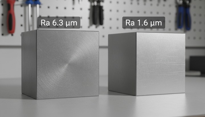
• Ra 3.2–6.3 μm works for general surfaces or non-critical interfaces.
• Ra 1.6–3.2 μm suits many precision mechanical fits.
• Ra below 1.6 μm is often reserved for sealing surfaces, sliding interfaces, or cosmetic applications.
It is also useful to identify which surfaces are functional and which are cosmetic. Aesthetic surfaces may need uniform appearance, but precision sealing surfaces may require specific roughness for performance. If both are labeled the same, you risk over-finishing non-functional areas.
A simple rule is: apply stricter Ra values only where surface-to-surface interaction is essential and allow standard “as-milled” finishes everywhere else. This alone can cut significant machining time while preserving product behavior.
How Tolerance Relaxation Reduces Machining and QA Time?
Relaxing tolerances on non-critical features produces savings across multiple stages of machining. The effect is not incremental—it is compounding. Machinists can run faster feeds, reduce tool changes, and use fewer finishing passes. Inspectors can take fewer measurements and rely on simpler gauges rather than CMM scans. Scrap rates decrease because production variation is more easily absorbed within acceptable limits.
You can see the cumulative impact in a simplified view:
| Design Relaxation | Result in Machining | Result in QA |
|---|---|---|
| Larger dimensional tolerance | Fewer finishing passes, faster feeds | Sampling instead of 100% inspection |
| Higher Ra value allowed | Reduced polishing/finishing operations | Fewer surface checks |
| Simplified GD&T callouts | More flexible toolpaths, easier setups | Shorter CMM programs and fewer setups |
| Consistent datum scheme | More stable machining strategy | Faster, more repeatable measurement routines |
This is why many experienced CNC suppliers encourage early DFM reviews. Small changes—such as widening a hole tolerance, increasing a radius, or relaxing the flatness requirement on a non-functional surface—can save seconds on each part. Across a batch or a long-term production program, those seconds turn into hours of machine time saved.
The key principle is simple: precision is valuable when it supports function, and costly when it does not. By relaxing tolerances only where appropriate and maintaining precision where needed, you achieve an ideal balance of cost, manufacturability, and performance.
Material Selection and Blank Optimization
Choosing the right material and blank size is one of the most powerful levers to reduce CNC machining cost without compromising performance. When you select a machinable, readily available grade and pair it with a well-optimized blank, you cut cycle time, reduce scrap, and stabilize pricing across the life of the project.
In practice, material and blank decisions affect tool life, cutting speeds, stock removal volume, fixturing, and even QA requirements. If you start by defining functional requirements (strength, stiffness, temperature, corrosion, regulatory constraints) and then work backwards to the “easiest” material and blank strategy that meets them, you can often remove 15–30% of machining cost compared to a default “over-spec” choice.
From a cost perspective, you should treat material selection and blank optimization as a joint decision. You do not only choose “aluminum vs steel vs plastic”; you choose how close the starting blank is to the final shape, and whether solid machining, forging, extrusion, or casting plus CNC is the most economical route over the full volume range.
Choose Materials With Good Machinability
If two materials can both meet the mechanical and environmental requirements, the one with better machinability is usually the smarter choice for CNC cost. Material machinability directly controls cutting speeds, tool wear, and achievable surface finish, which means it has a strong impact on machine-hour cost.
For example, common aluminum alloys such as 6061 and 6082 typically allow much higher cutting speeds than stainless steels like 304 or 316, while also generating less tool wear. In many real-world jobs this results in shorter cycle time and lower tool cost per part, even if the raw material price per kilogram is similar or slightly higher. You can refer to machinability data from sources like and for benchmark values.
When you make material choices with machinability in mind, it helps to:
-
Start from the minimum performance, not the maximum. Define load, temperature, corrosion, and safety margins, then select the “simplest” grade that satisfies them.
-
Prefer free-machining or machining-optimized grades (where available) for high-volume parts, as they often include additives that improve chip breaking and tool life.
-
Avoid unnecessarily hard or abrasive materials for non-critical components, because every increase in hardness usually means more cost per minute on the machine.
-
Discuss tool strategy with your supplier. A shop experienced in CNC aluminum housings and brackets might, for example, guide you towards alloys they already cut efficiently for similar projects.
By codifying machinability as a standard column in your internal material selection process, you make it easier for engineering and procurement teams to jointly control CNC machining cost.
Compare Cost vs. Performance Across Aluminum, Steel, and Plastics
Most CNC machined parts fall into three broad material families: aluminum, steel (including stainless), and engineering plastics. Each group brings different performance and cost characteristics. You reduce machining cost when you match material family to real-world use case instead of habit or legacy choices.
A simple way to visualize trade-offs is shown below.
| Material family | Relative raw material cost (typical) | Machinability (general trend) | Typical CNC applications | Cost observations |
|---|---|---|---|---|
| Aluminum alloys | Low to medium | Very good to excellent | Housings, brackets, heat sinks, structural frames, machine parts | Often the best balance of strength, weight, and machinability; good candidate for cost-sensitive machined parts. |
| Carbon steels | Low | Good to moderate | Shafts, gears, structural components, fixtures | Attractive raw cost, but higher cutting forces and potential heat treatment add cost; good for high-strength needs. |
| Stainless steels | Medium to high | Moderate to poor (austenitic grades) | Food, medical, chemical, marine parts | Corrosion resistance comes with lower machinability and more tool wear, so geometry must be kept as simple as possible. |
| Engineering plastics | Medium (per kg) but light weight | Excellent (for most grades) | Insulators, covers, light-duty components, medical devices | Very fast to machine, but require care with clamping and heat; ideal when loads are modest and weight reduction matters. |
This table is a starting point, not a rule book. For example, if you design a stainless manifold but most media is non-corrosive and working temperatures are modest, switching to a high-strength aluminum alloy with suitable surface treatment can reduce CNC machining time and total cost significantly. When you work with a supplier that handles both CNC machined aluminum parts and steel components on a daily basis, they can benchmark your design against similar parts to suggest realistic alternatives.
Use Standard Stock Sizes to Minimize Waste
Even if you have chosen a cost-effective material, the blank size and format can still make the part expensive. Every millimeter of extra stock in thickness or diameter becomes chips that you pay to remove, and this also increases machine time and tool wear.
Most mills and distributors follow standard bar, plate, and tube sizes. If your design requires a 52 mm diameter, but local stock comes in 50 mm and 55 mm, machining from 55 mm bar means more roughing time and scrap. Sometimes, small design adjustments—such as reducing the OD slightly or optimizing wall thickness—allow you to fit into a more efficient stock size.
Practical ways to optimize blanks include:
-
Align key dimensions with standard stock sizes for plate thickness, bar diameter, or extrusion profiles.
-
Discuss blank strategy early with your CNC supplier. They can advise whether saw-cut plate, round bar, extrusions, or pre-forms are most economical for your volume and geometry.
-
For flat parts, consider nesting multiple components on a common plate thickness, so material purchasing and cutting are consolidated.
-
When parts are similar in size, standardize a few blank sizes across your product family to simplify purchasing and reduce waste.
When you align design dimensions with real-world material supply, you turn blank selection into a repeatable cost control tool instead of an afterthought.
When to Combine Casting + CNC to Lower Material Cost?
For large, bulky, or high-volume components, machining everything from solid stock is rarely the cheapest long-term solution. In such cases, combining a near-net-shape process (like die casting, sand casting, or forging) with CNC finishing can dramatically reduce material removal and cycle time.
This hybrid approach usually makes sense when:
-
The part has high volume and a stable geometry over the product life.
-
You remove a large amount of material in the current design (deep pockets, heavy thickness reductions).
-
The component has an “envelope” that can be formed economically by casting or forging, while functional surfaces, threads, and sealing areas are finished by CNC.
-
Tolerance and surface finish requirements are tight only in specific zones.
With aluminum die casting plus CNC, for example, you can create complex housings and brackets where most of the material and internal cavities are formed in the die. CNC then focuses on precision bores, sealing surfaces, and critical interfaces. This strategy lowers not only raw material and machine time, but often simplifies fixturing and improves repeatability.
Of course, casting introduces tooling investment and process constraints such as draft angles, wall thickness limits, and porosity considerations. For that reason, the decision to switch from solid machining to casting + CNC should be volume-driven and based on a clear ROI analysis over expected lifetime demand. Data from manufacturing economics and casting processes, such as those summarized in , can help structure the discussion.
Material Availability and Lead Time Considerations
The best material on paper is useless if it creates supply chain risk. Availability, regional stocking practices, and lead time can quickly turn a technically neat design into a delayed and expensive project. When you design for CNC machining cost, you should check not only what is possible, but what is practical in your supplier’s region.
Some pragmatic rules that help:
-
Prefer widely stocked alloys and sizes that your supplier already buys in volume. Local mills and service centers are more likely to keep common grades on the shelf, which shortens lead time and stabilizes pricing.
-
Avoid exotic or rarely used materials unless truly necessary for safety or regulatory reasons. These often come with MOQ constraints, longer lead times, and volatile prices, all of which add cost and complexity.
-
For strategic parts, consider dual-sourcing compatible materials (for example, two equivalent aluminum grades) so that minor supply issues do not disrupt your production plan.
-
Align your demand pattern with your supplier’s purchasing strategy. For repeat orders, a long-term forecast allows them to stock critical materials in advance and negotiate better pricing, which indirectly reduces your CNC machining cost.
When you treat material availability as part of your design criteria, you protect both cost and delivery performance. In many projects, early discussion with a manufacturing partner that has solid relationships with material suppliers and experience across multiple industries leads to simpler material selections that still satisfy engineering requirements, while keeping CNC machining cost under tighter control.
Design for Fewer Setups and Simplified Fixturing
Designing parts so they can be machined in as few setups as possible, with simple fixtures, is one of the fastest ways to reduce CNC machining cost. Each extra setup adds non-cutting time, operator handling, and alignment risk. In many lean programs, systematic setup reduction (SMED) has cut changeover time by 30–50%, which directly lowers cost and improves machine utilization. When you treat setups and fixturing as design variables, not just shop-floor issues, you gain significant leverage on price.
From a cost perspective, you pay for three things every time the part is reclamped: the time to orient and clamp it, the cycle time to re-probe datums, and the risk of scrap if alignment is imperfect. Extra setups also force more complex fixtures and more manual checks. If you can get a part down from four setups to two, you often unlock cheaper machine choices, safer automation, and more predictable quality. This is why we encourage engineering and procurement teams to put “setup count” on the same level as geometry, tolerances, and material when they review new designs.

Align Features to Reduce Rotations and Re-Clamping
If you design the part so most features lie in a small number of planes, the machinist can reach everything in fewer setups. The more you keep critical features aligned in one or two orientations, the lower your setup time and cost. Every time a part rotates from top to side to back, someone must unclamp it, reorient it, and re-establish datums.
When you place holes, pockets, and faces on random angles, the shop may need 3-axis machining with multiple repositionings, or even a 5-axis machine, just to reach everything. These choices increase hourly machine rate and programming effort. By contrast, if you cluster features on orthogonal faces that can be accessed in one or two vice orientations, the shop can use straightforward 3-axis programs and standard vices, which cost less per hour and are easier to automate.
A practical way to do this is to start from the “primary clamp face” and draw a simple grid of accessible planes: top, front, and right side. Place most features on these planes and align threaded holes and bosses along common axes. When you must add angled features, consider whether they are really essential or can be handled by secondary operations such as simple drilling fixtures.
Use Symmetry and Consistent Datums
Symmetry is not only good for part performance; it is powerful for cost control. Parts that are symmetric around one or two axes are easier to clamp, probe, and flip. The machinist can reuse the same jaws and datums for multiple faces, which reduces setup variation and time.
When your drawing uses a clear, consistent datum structure, inspection and re-clamping become simpler. Quality teams can reference the same primary and secondary datums for all dimensions, and machinists can probe the same surfaces after each flip. This reduces the number of coordinate systems and work offsets they must manage, which directly cuts non-cutting time and the risk of operator error.
If you have design freedom, consider these rules of thumb:
• Make one face clearly the “primary mounting face,” wide and flat enough for secure clamping.
• Align key features (bores, slots, bosses) relative to this face and one perpendicular face.
• Use symmetry so that flipping the part 180° exposes new features while keeping the same clamping approach.
This type of geometry also simplifies the use of modular fixtures and tombstones. These systems pay back quickly in medium to high volumes because they let shops load multiple parts with consistent datums, then run unattended cycles.
Avoid Features That Require Custom Fixtures
Custom fixtures can be valuable for very high volume programs, but they are expensive to design, build, and maintain. Industry guides on CNC fixtures point out that while fixtures improve throughput and accuracy, they also add investment and setup complexity, so they must be justified by volume and repeatability.If your part design forces the supplier to build a dedicated fixture for a small or uncertain volume, your unit cost will increase.
Features that often push a design into custom-fixture territory include:
• Odd, non-parallel faces as the only load-bearing surfaces.
• Very small contact areas that make standard jaws unstable.
• Complex curves that must be referenced as clamping surfaces.
• Features on multiple non-orthogonal angles that must be held simultaneously.
When you see these patterns in your model, step back and ask whether you can add simple pads, bosses, or temporary “sacrificial tabs” that give the machinist stable clamping surfaces. In many projects, adding two small flats or a removable clamping ear is far cheaper than commissioning a full custom fixture. These temporary features can be removed in a final, simple operation with minimal cost.
If you anticipate ongoing volume and want to justify a dedicated fixture, discuss this early with your CNC partner. You can co-design a fixture that supports future part variants or families, which spreads the cost over several SKUs rather than a single part number.
Convert Multi-Sided Machining Into 2-Sided Operations
Every time a part requires three or four distinct clamp orientations, you add changeovers, risk, and cost. Lean manufacturing literature on changeover reduction (SMED) shows that standardizing and minimizing setups can dramatically increase overall equipment effectiveness (OEE) and reduce inventory. For CNC machining, a good design objective is to make most parts manufacturable in two main setups whenever possible.
To move from four-sided to two-sided machining, consider:
• Consolidating side features into top and bottom faces where possible.
• Using cross holes drilled from two perpendicular faces instead of several different sides.
• Adding through-holes that allow drilling from both directions in one clamp orientation.
• Using a machining strategy where a 3-axis or 4-axis machine rotates the part around a single axis, but still treats the operation as two core setups.
You can also take advantage of pallets and tombstones. For example, a shop might mount your part in a vertical machining center so that Setup 1 machines all top and side features via a rotary axis, and Setup 2 finishes the bottom. From your perspective as a designer, the key is to avoid demanding a unique clamp orientation for each small feature. If a feature can be reoriented in your CAD model to align with existing faces without hurting function, that change often translates directly to fewer setups and lower CNC machining cost.
For parts that still need complex access, consider whether 5-axis machining is actually cheaper than many 3-axis setups. With thoughtful design, a single 5-axis setup can replace three or four manual re-clamp operations, especially for tight-tolerance features that must stay in perfect relationship to each other.
Setup Optimization for Repeat Orders and Long-Term Production
One-time prototypes are important, but most cost reduction comes from repeat orders over the life of the product. If your design supports stable, repeatable setups, your supplier can build standard programs, fixtures, and inspection routines that improve with every batch. Over time, this reduces changeover time, scrap, and unit cost.
Lean case studies on setup reduction show that once a process is standardized, setup time can drop to a small fraction of the original, sometimes to under 10 minutes in high-performance environments. That level of performance is only possible when the part design is stable and the fixturing is simple and robust. When you constantly change features, move datums, or introduce new orientations, the shop cannot lock in a mature process.
From an engineering and procurement standpoint, you can support long-term optimization by:
• Freezing datums and core geometry once the part reaches production, and managing changes carefully.
• Grouping parts into “families” that share similar clamping strategies and feature orientations.
• Requesting that your supplier document best-known setups and share ideas for minor design tweaks that would simplify them further.
This is also where a one-stop partner who offers CNC machining, die casting, and finishing can help. For example, you might start with fully machined in early phases, then shift to near-net casting plus machining as volumes grow, while keeping the same basic setup concept. That continuity protects your quality and shortens ramp-up whenever demand increases.

For external reference on setup reduction and fixturing methods, you can consult lean manufacturing resources on SMED and workholding, such as the SMED overview on LeanProduction and independent guides on CNC jigs and fixtures, which explain how standardized fixtures and reduced changeovers improve cost and throughput in machining environments.
Prototype vs. Production: Designing for Scalability
When you design only for prototypes, you often “freeze” expensive features into the final product. Scalable CNC parts start with a design that works for both low-volume validation and long-run production. In this section, we look at how to bridge that gap so you avoid redesigns, repeated tooling changes, and unexpected machining cost spikes when volumes increase.
Why Prototype-Friendly Designs May Fail in Production?
Many teams optimize the first prototypes for speed and flexibility. You might over-machine from a solid block, accept awkward setups, or ignore tool life because you only need 5–20 pieces. This approach is fine at the early stage, but serious problems appear when the same design is pushed into hundreds or thousands of parts.
Typical failure modes include:
-
Parts that require multiple complex setups on 3-axis machines, driving up machine time.
-
Deep pockets and thin walls that are stable in low volume but unstable in continuous production.
-
Tight tolerances and cosmetic finishes that add little functional value but dominate cycle time and scrap rates.
-
Material choices that are easy to get in small billets but expensive or difficult to source for long-term runs.
From a cost perspective, the risk is clear: what was acceptable at 10 pieces becomes uncompetitive at 1,000 pieces. This is why we always recommend a “prototype with production in mind” mindset. During the prototype phase, start noting which features will be painful to run in larger batches and which can be simplified or standardized later.
To reduce this risk, it helps to:
-
Flag prototype-only features that you know will be removed or relaxed later.
-
Mark “production-critical” areas on 2D drawings so your CNC supplier can comment on long-term manufacturability.
-
Ask your supplier early which features they see as red flags once you move into continuous production.
If you already have parts that are expensive to scale, a joint DFM review with your CNC partner can highlight which changes will deliver the largest cost reduction per design revision, instead of chasing cosmetic tweaks that do not move the needle.
Transitioning From Rapid Prototyping to CNC Production
Most product development workflows now combine several methods: 3D printing for early validation, CNC machining for functional prototypes, and then CNC or casting plus CNC for production. The challenge is to plan the handover from “fast and flexible” to “repeatable and economical”.
A practical transition path usually looks like this:
-
Early prototypes
-
3D printing or quick CNC from standard stock material.
-
Focus on fit, basic function, and ergonomic checks.
-
Minimal optimization; speed is the priority.
-
-
Design-verified CNC prototypes
-
Machined to near-production tolerances and surface finishes.
-
Introduction of realistic fixturing and tooling strategies.
-
Initial discussion of production quantities and cost targets.
-
-
Pilot run / pre-production
-
Batch size in the tens or low hundreds.
-
Use near-final programming, fixturing, and inspection plans.
-
Measure real cycle time, tool wear, and achievable scrap rates.
-
-
Full production
-
Stable NC programs, standardized setups, documented inspection plans.
-
Continuous improvement based on real data from the pilot run.
-
During the transition from prototype to CNC production, the design should evolve as well. You might increase wall thickness to reduce vibration, adjust radii to use more robust tools, or consolidate features so they can be machined in fewer setups. When you involve your CNC supplier at the design-verified prototype stage, they can provide specific advice like:
-
Where a 3D-printed fillet should be converted into a standard end mill radius.
-
Which threaded holes should be shortened or standardized for faster tapping.
-
How to reorient the part to cut it in two setups instead of four.
For readers working on design rules and internal standards, this is also the right moment to document what you are learning into your own “DFM for CNC” checklist and share it across engineering and procurement.
Volume-Based Design Adjustments for Cost Efficiency
A part that is economical at 50 pieces per year often looks very different from a part that will run 5,000 pieces per year. Designing with clear volume scenarios in mind is one of the simplest ways to control CNC machining cost.
The following table gives a high-level view of how design priorities shift with volume:
| Volume Range | Design Priority | Typical Design Choices |
|---|---|---|
| 1–20 pcs (prototype) | Speed and flexibility | Machining from solid, more setups acceptable, quick material choice |
| 20–200 pcs (pilot / niche) | Balance cost and agility | Simplified features, reduced setups, standard tools and threads |
| 200–2,000 pcs (series) | Unit cost and process stability | Optimized fixturing, rationalized tolerances, better material deals |
| 2,000+ pcs (mass production) | Long-term cost and automation potential | Casting + CNC, custom fixtures, tool life optimization |
For example:
-
At very low volume, a deep pocket with sharp internal corners might be acceptable if your supplier can machine it with a small tool and a slow feed rate.
-
At medium volume, you may want to introduce a radius that matches a more robust cutter, even if it slightly changes the internal geometry.
-
At high volume, you might redesign the part as a casting with machined pads, saving raw material and cutting time, while keeping critical interfaces machined for accuracy.
From a procurement perspective, it is helpful to share your realistic annual volume and ramp-up plan with the supplier, not just the first order quantity. This allows your CNC partner to tell you:
-
Whether your current design is better suited for low-volume machining only.
-
When a shift to an alternative process (casting, extrusion plus CNC, or modular design) will start to pay off.
-
What design changes are required to unlock those savings.
When engineering and sourcing teams treat volume as a design input, not just a purchasing parameter, they can align on which features to keep, which to simplify, and when to invest in better tooling or fixtures.
Standardizing Features for High-Mix, Low-Volume Projects
Many B2B companies, especially in machinery, robotics, and industrial equipment, live in a high-mix, low-volume world. You may run dozens or hundreds of unique part numbers every year, with small batches for each. In this environment, the biggest cost enemy is not only cycle time but changeover time and engineering overhead.
Standardization is the most effective design lever here. Instead of treating every new part as a blank canvas, you can:
-
Reuse standard hole sizes, threads, and counterbores across families of parts.
-
Align radii, chamfer sizes, and wall thicknesses to a handful of internal “house standards.”
-
Define internal rules for minimum fillet radii, minimum wall thickness, and maximum cavity depth for common materials like 6061-T6 aluminum or 304 stainless steel.
-
Use common datum schemes so that similar parts can share fixtures and inspection programs.
For the CNC shop, this means:
-
Fewer tool changes between jobs.
-
Reusable fixtures and clamping schemes.
-
Copy-paste NC strategies with minor adjustments instead of new programming from scratch.
-
Shorter setup and prove-out time for every new reference.
From your side, you gain:
-
More predictable quotations, because parts look familiar to the supplier.
-
Lower risk of design errors, since you work within a proven “design envelope.”
-
Faster onboarding of new engineers who can follow the same CNC-oriented standards.
A practical approach is to create internal design templates for your most common part types (brackets, plates, housings, shafts). Each template specifies default dimensions, corner radii, hole standards, and tolerances that are already validated by your CNC supplier. When a new project starts, engineers can adapt these templates instead of designing from zero, and your partner can machine them more efficiently from day one.
If you share your key part families and volume structure with a manufacturing partner like HM, we can help you define these standards based on real shop-floor data. This closes the loop between design intent and machining reality, and it makes cost reduction through smart design a repeatable process, not a one-time exercise.
How to Work With Your Supplier to Reduce CNC Cost?
Working closely with your CNC machining supplier is one of the most effective ways to reduce cost across prototypes, pilot runs, and full-scale production. A supplier sees hundreds of part designs every month, so they know which features trigger additional setups, slow toolpaths, unnecessary tolerances, or expensive materials. When you communicate clearly, share complete technical data, and involve them early, you gain access to this knowledge before cost becomes locked into your drawing.
Collaboration works best when both sides understand the same goal: create a stable, manufacturable design that meets functional requirements with the lowest total cost. This includes machining strategy, inspection planning, long-term material sourcing, and part-family standardization. When you treat the supplier as a technical partner—not just a quote provider—you avoid rework, engineering revisions, and procurement surprises later.
What to Include in an RFQ for Cost-Optimized Quotes?
A cost-optimized RFQ gives your supplier the information they need to provide an accurate quote and a realistic manufacturing plan. Missing or unclear data often leads to conservative pricing, because the supplier must assume the worst-case scenario for tolerances, surface finish, inspection workload, and setups.
To reduce CNC machining cost at the RFQ stage, include:
-
3D model (STEP/X_T) and fully defined 2D drawings with tolerances, finishes, and critical features marked.
-
Material specifications, including acceptable alternatives—this gives the supplier flexibility to recommend more machinable or more available grades.
-
Expected volumes (prototype, pilot, annual, and full production). This guides decisions on fixtures, tooling, and blank strategy.
-
Function of the part so the supplier can understand which features must remain tight and which can be relaxed.
-
Surface finish requirements and whether cosmetic surfaces are single-sided or multi-sided.
-
Inspection level (sampling vs. 100% inspection) and whether CMM reports are mandatory.
-
Assembly relationships, which help clarify datum priorities.
-
Packaging or handling constraints, especially for delicate or cosmetic parts.
You can also ask your supplier to propose:
-
Cost-saving material substitutions.
-
Alternate machining paths (3-axis vs. 5-axis).
-
Recommendations for simplifying geometry or tolerances.
A complete RFQ is one of the simplest ways to achieve predictable pricing and reduce risk of costly engineering changes after quoting.
Running a DFM Review With Your Manufacturing Partner
A structured Design for Manufacturability (DFM) review is where most cost reduction opportunities appear. This meeting—often 20–40 minutes for a typical CNC part—lets the supplier highlight features that increase machining time or inspection cost, and explain why certain design choices need adjustment.
Typical DFM topics include:
-
Deep pockets, sharp internal corners, and thin walls that slow cutting speeds.
-
Tolerance stacks that force additional setups or expensive measurement strategies.
-
Features that cannot be reached with standard tooling or require 5-axis access.
-
Stock-size mismatches that cause unnecessary waste or long roughing cycles.
-
Locations where adding a radius, changing a thread depth, or adjusting cavity geometry dramatically improves machinability.
A productive DFM review has two traits:
-
The designer is open about functional limits—what can change and what cannot.
-
The supplier explains the reasoning behind each recommendation, often with examples from similar past projects.
When both sides understand the “why,” design decisions become faster and more cost-effective. In many cases, 2–3 edits after a DFM review can remove 10–20% of machining cost with zero loss of function.
Typical Supplier Recommendations That Lower Cost
Experienced CNC suppliers share a set of common patterns—they see which features increase machining time and which simplifications have minimal functional impact. Many cost-reduction suggestions fall into predictable categories:
-
Increase internal radii to match standard end mill sizes.
-
Reduce cavity depth or add step features to avoid long-reach tools.
-
Standardize hole sizes across the part so one drill or tap can be reused.
-
Relax tolerances on non-critical dimensions and allow standard general tolerances.
-
Simplify datum schemes to reduce inspection complexity.
-
Change thread lengths so tapping can be done with standard tools.
-
Remove or minimize engraved logos and cosmetic chamfers.
-
Change the parting strategy to enable two-sided machining instead of three or four setups.
-
Reorient the part so critical features are machined in more stable setups.
When you review suggestions from your supplier, remember that their goal is not only cost reduction—it is process stability. The easiest parts to run are the most repeatable, and repeatable parts always cost less over the product lifecycle.
Eliminating Iterations Through Early Technical Collaboration
Engineering iterations are expensive. When a part moves through prototype, pre-production, and mass production without consistent technical communication, small issues stack up—misunderstood tolerances, ambiguous GD&T callouts, unoptimized features, or unplanned inspection steps. Each iteration adds days or weeks to the schedule and increases cost.
You can prevent most of these issues through early collaboration:
-
Schedule a DFM meeting before finalizing the drawing.
-
Share functional requirements and assembly relationships so the supplier understands what must remain strict.
-
Ask the supplier to simulate toolpaths or provide machining strategy notes for critical features.
-
Review inspection expectations early—CMM or manual gauges—and align on what is necessary.
-
Validate machinability using prototypes produced under near-production conditions, not quick-turn shortcuts.
When engineers and machinists collaborate early, the first production batch behaves like a mature process—not an experiment that needs multiple corrections.
Building Long-Term Cost Reduction Into Production Runs
CNC cost reduction does not end after the first production batch. In long-term relationships, suppliers usually improve cycle time, tooling strategy, and setup efficiency naturally as they repeat the job. If you coordinate these improvements strategically, you can turn incremental gains into significant cost savings.
Strategies for long-term optimization include:
-
Volume forecasting that lets the supplier optimize material purchasing, build semi-dedicated fixtures, or stock standard blanks.
-
Part-family standardization, which allows reuse of programs, fixtures, tools, and inspection plans.
-
Process capability monitoring, so tolerances can potentially be relaxed once real data shows adequate margin.
-
Continuous improvement cycles, where the supplier proposes minor geometry adjustments between batches.
-
Switching manufacturing processes as volumes rise—for example, moving from full machining to casting + CNC once the ROI becomes favorable.
From your side, stability and transparency are the biggest enablers. When suppliers have confidence in long-term demand, they invest in:
-
Better fixtures.
-
Higher-efficiency toolpaths.
-
Tool life optimization.
-
Automated handling or pallet systems.
These investments become cost savings that flow directly into your unit price over time.

CNC Cost Reduction Checklist for Engineers
When you are under time pressure, a simple checklist helps you catch the biggest CNC cost drivers before you release a drawing. A good rule of thumb is to ask yourself: “If I were paying for machining time, setups, and scrap from my own budget, what would I change on this drawing?” The following checklists are designed to be used in design reviews and RFQs.
Geometry and Feature Optimization Checklist
Before finalizing your 3D model:
-
Have I simplified overall geometry wherever possible, avoiding unnecessary steps, undercuts, or non-functional contours?
-
Are all internal corners designed with tool-friendly radii that match standard end mills instead of forcing micro-tools?
-
Have I limited pocket depth and avoided long, thin ribs or walls that will chatter or deflect during machining?
-
Did I remove engraved text, logos, or decorative chamfers that do not contribute to function or safety?
-
Have I checked whether two or more parts in the assembly could be combined into a single part to cut machining and assembly cost?
A quick internal review against these points can remove many of the features that silently add hours of programming and cutting time.
Tolerance and Surface Finish Checklist
For your tolerances and finishes:
-
Have I clearly marked critical features and left standard tolerances on non-critical ones?
-
Are there dimensions called out tighter than ±0.05 mm (±0.002 in) simply because of default templates, rather than real functional needs?
-
Did I avoid specifying tight flatness or position tolerances on large surfaces unless they are essential?
-
Are surface roughness values limited to the areas that truly need 1.6 µm Ra, 0.8 µm Ra, or 0.4 µm Ra, while allowing 3.2 µm Ra as default elsewhere?
-
Have I checked that my geometric dimensioning and tolerancing (GD&T) scheme uses a clear and achievable datum structure?
Remember that industry data shows tight tolerances and ultra-smooth finishes can increase machining costs by several times compared to standard levels, mainly through extra passes, slower feeds, and more inspection.
Material and Blank Size Checklist
Before locking in your material callout:
-
Have I selected a machinable alloy instead of an unnecessarily hard or gummy grade, where design allows?
-
Did I check whether a different alloy or temper could meet strength or corrosion needs at lower machining cost?
-
Is the specified blank size close to the final envelope, avoiding large amounts of wasted stock?
-
Have I aligned the part orientation with common extrusion, plate, or bar sizes to simplify sourcing?
-
For stable, high-volume parts, have I evaluated whether casting plus CNC machining could reduce material and roughing cost?
Linking this checklist with your procurement colleagues helps you avoid situations where material is available on paper but has long lead times or minimum order quantities that make small batches very expensive.
Setup and Fixturing Checklist
-
Did I group functional features so they can be machined from as few orientations as possible?
-
Are key datums aligned to faces that are easy to clamp, not to small isolated surfaces?
-
Have I avoided features that require expensive custom fixtures when a simpler design could use standard vises or jaws?
-
Did I discuss with the supplier whether switching to 4-axis or 5-axis setups could eliminate re-clamping in production?
-
For repeat orders, have we agreed how fixtures and programs will be maintained and reused to keep costs stable?
Thinking through setups early keeps you out of the situation where a part is technically machinable, but only with time-consuming manual handling that erodes margins.
RFQ and Documentation Checklist
Finally, before sending your RFQ:
-
Does the RFQ package include clean 3D and 2D data, not screenshots or incomplete sketches?
-
Have I documented expected annual volume, ramp-up path, and order pattern?
-
Did I clearly separate must-have requirements from “nice-to-have” preferences to give the supplier room for optimization?
-
Have we requested a DFM review as part of the quotation process, not as an afterthought?
-
Is there a named contact on your side for technical questions, so the supplier is not forced to guess?
A disciplined checklist culture turns cost-reduction from a one-off exercise into a routine part of design and sourcing.
Frequently Asked Questions on CNC Cost Reduction by Design
Many engineering and procurement teams ask similar questions when they first start to focus on design-driven CNC cost reduction. Addressing these directly can speed up internal alignment and give you a clear starting point for your next project.
What Design Changes Have the Biggest Impact on CNC Machining Cost?
The largest cost impact usually comes from simplifying geometry, reducing setups, and optimizing tolerances. Complex pockets, deep thin walls, and undercuts drive program time, tool wear, and scrap. Multiple orientations and re-clamping add non-cutting time that you still pay for. Overly tight tolerances and ultra-smooth finishes require slower feeds, extra passes, and more inspection.
Industry experience and academic reviews show that decisions taken in the design phase typically lock in 70–80% of the final product cost, so even small changes at this stage can have a compounding effect downstream. If you only have time for a few checks, focus on radii, wall thickness, number of setups, and which tolerances truly control function.
How Can I Reduce CNC Cost Without Changing the Material?
If you cannot change the material due to standards or certification, you can still reduce cost by:
-
Relaxing non-critical tolerances to default machining levels.
-
Reducing the number of operations by grouping features and aligning datums.
-
Shortening threads, minimizing spotfaces, and removing ornamental chamfers.
-
Allowing standard surface roughness wherever possible instead of specifying premium finishes.
-
Working with your supplier to adjust toolpaths, feeds, and speeds based on real production data.
In many cases, process optimization and design simplification can deliver double-digit cost reductions even when the material grade is fixed by your customer or by industry norms.
Is 5-Axis Machining Always More Expensive Than 3-Axis?
5-axis machining often has a higher hourly rate due to machine investment and operator skill, but it is not automatically more expensive at the part level. When used correctly, 5-axis setups can:
-
Reduce the number of fixtures and clamping operations.
-
Eliminate secondary operations on separate machines.
-
Improve access to complex features without custom tooling.
For some geometries, a single 5-axis setup can replace three or four 3-axis setups, which reduces handling time, stack-up error, and scrap. The right question is not “Is 5-axis more expensive?” but “For this geometry and volume, which combination of machines and setups gives the lowest total cost?”
When Should I Consider Switching From Solid Machining to Casting + CNC?
Casting plus CNC finishing becomes attractive when:
-
The part is geometry-rich but structurally efficient, such as housings, brackets, or complex covers.
-
Volumes are high enough that tool investment can be amortized over several years.
-
Material removal from solid billet dominates cycle time in your cost breakdown.
A typical path is to start with full machining for prototypes and early orders, then switch to die casting plus CNC once demand stabilizes and the design is frozen. At that point, the casting can provide near-net shape, and CNC focuses on critical surfaces, bores, and threads. This combination often reduces both material waste and machining time for mature projects.
For more background on cost reduction and manufacturing economics, you can reference neutral sources such as the entry on Wikipedia, which summarizes how design decisions influence overall project cost.
How Early Should I Involve My CNC Supplier in Design?
From a cost perspective, the answer is “as early as practical without slowing concept work.” Studies in engineering design show that most of the product’s cost and quality is determined during early design stages, long before detailed drawings are released.
A good pattern is:
-
Develop your initial concept and functional architecture internally.
-
Involve your CNC supplier when you have a stable 3D model for key parts, even before full detailing.
-
Run a short DFM session to adjust geometry, tolerances, and material before you lock the drawing.
-
Use prototype orders to validate not only function, but also process capability and cost structure.
The earlier you turn your supplier into a design ally instead of a last-step vendor, the more you benefit from their process knowledge and real-world cost data.
Conclusion — Smart Design as a Strategic Cost Advantage
Smart design is not only about making parts manufacturable; it is about turning design decisions into a durable cost advantage. By tackling geometry, tolerances, material, setups, and RFQ quality in a structured way, you protect performance while shifting cost out of machining time, scrap, and rework. The result is a part that is easier to quote, easier to produce at scale, and more resilient when demand changes.
If you want to apply these principles in real projects, the next step is to bring your supplier into the discussion early. Share your models, your constraints, and your long-term plans, and ask for honest DFM feedback tied to concrete cost drivers. If you are looking for a China-based partner who combines CNC precision machining, aluminum and zinc die casting, surface finishing, and assembly, you can learn more about HM’s capabilities on our and