


A DFM checklist for CNC machining helps you avoid redesign delays, unexpected costs, and long quoting cycles. When engineers send RFQs without checking manufacturability, suppliers often struggle to provide accurate pricing or timelines, leading to stalled projects.
Many teams face the same issue: parts look perfect in CAD but reveal geometric conflicts, tolerance conflicts, or material issues once machining starts. These prevent suppliers from giving a firm quote and trigger multiple rounds of clarification. This slows sourcing, reduces momentum, and increases engineering workload.
This guide shows you exactly how to prepare a complete, manufacturable CNC machining RFQ. You will learn how to validate geometry, set proper tolerances, choose the right materials, prepare correct drawings, and avoid the issues that raise cost or delay production.
Understanding DFM for CNC Machining
What Is DFM and Why It Impacts CNC Machining Cost, Lead Time & Quality?
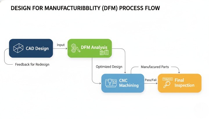
Design for Manufacturability (DFM) ensures a part can be produced efficiently, reliably, and at a predictable cost before machining begins. A proper DFM review identifies geometric conflicts, excessive tolerances, and material constraints that often trigger rework during quoting. When you address these issues early, you reduce machining time and avoid cost drivers such as unnecessary setups or special tooling requirements.For a formal definition, see the design for manufacturability (DFM) definition.
DFM has a direct influence on your CNC machining cost, lead time, and quality. Poorly optimized designs create longer cycle times, unstable tolerance performance, or difficult tool access. These conditions force suppliers to slow down feeds, add custom fixtures, or reject risky features, which increases the overall price. A well-executed DFM check lowers risk, strengthens process capability, and helps your supplier deliver consistent parts from prototype to mass production.
The Difference Between DFM Review and Design Review
A design review evaluates whether a part meets its functional and engineering requirements. It focuses on performance, strength, assembly, and end-use behavior. A DFM review, however, examines how easily that same part can be produced. It checks manufacturability factors such as cutter reach, tolerance stack-ups, tool selection, and machining strategies. Both reviews are essential, but they solve different problems.
In practice, many RFQs fail because teams assume a functional design is automatically manufacturable. DFM reveals hidden issues such as non-standard hole depths, unrealistic surface finish demands, or internal corners impossible to mill. A strong RFQ requires both reviews: one ensures the design works; the other ensures it can actually be produced in a stable, repeatable, and cost-effective way.
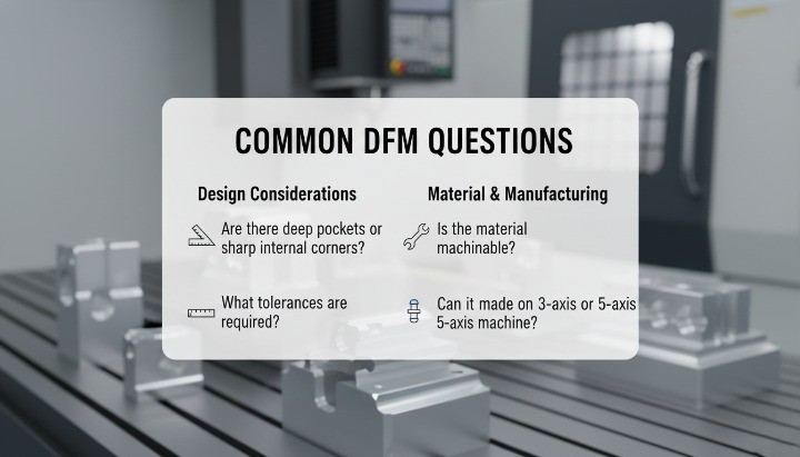
How CNC Suppliers Perform DFM Analysis (What They Actually Check)?
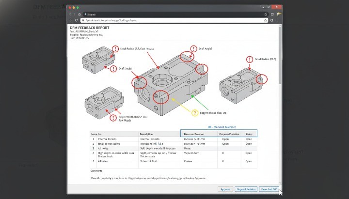
Suppliers follow a structured checklist when reviewing CNC files during the RFQ stage. They evaluate geometry complexity, identify cutter limitations, and confirm whether the requested tolerances match the capabilities of their machines. They also inspect unclear or missing dimensions, file inconsistencies, and material notes that affect machining strategy. These checks allow the supplier to decide whether the part can be produced with standard workflows or requires special treatment.
A typical supplier DFM analysis includes access verification, wall stability checks, hole manufacturability, pocket depth ratio, and feature orientation. They also examine GD&T symbols for potential conflicts, review surface finish requirements, and assess material machinability. The supplier’s goal is to eliminate ambiguity and ensure they can deliver the part without excessive risk. A clear, manufacturable design shortens the quoting cycle and improves accuracy, which benefits both the engineering team and the supplier.
The Complete DFM Checklist Before Sending Your CNC Machining RFQ
1. Validate the Part Geometry
You should validate the geometry early because clear geometry drives better manufacturability, accurate pricing, and faster responses from suppliers. A correct model aligns with design for machining, design for CNC machining, and general design for manufacturability expectations. When the model follows standard machining practices, the supplier can evaluate the required operations, the machining layout, and tool accessibility without unnecessary back-and-forth.
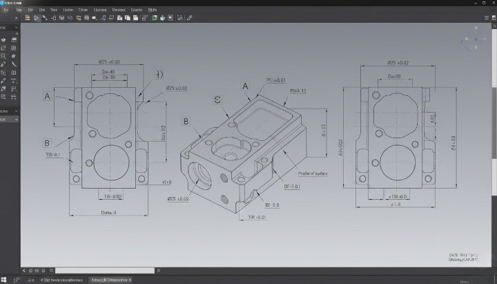
You can check manufacturable geometry by reviewing areas such as sharp internal corners, undercuts, thin ribs, and deep cavities. These features often trigger additional setups, which increases cost in dfm manufacturing evaluations. Clear geometry across STEP and PDF views reduces ambiguity during DFM analysis and improves understanding of the manufacturing design process. Each validated feature strengthens the overall dfm design and ensures alignment with recognized design for manufacturing principles.
2. Check Critical Tolerances & GD&T
You should define tolerances clearly because they directly influence what is DFM, machining time, and quality. Suppliers use your GD&T to understand functional needs and conduct accurate dfm analyse and dfm check procedures. Excessively tight tolerances increase setup time, inspection requirements, and cost, especially in design and manufacturing process planning.
You can prioritize only the dimensions that matter. This helps avoid unnecessary complexity in the design for manufacturing process and aligns with DFM principles used across industries. When your tolerance scheme is structured, the supplier can reference dfm review meaning, apply dfm engineering considerations, and give clearer dfm feedback. A precise GD&T drawing also supports downstream tasks such as certification audits and design for manufacturability guidelines.
3. Review Wall Thickness Requirements
You should confirm wall thickness to reinforce structural stability and prevent deformation during machining. Thin sections cause vibration, deflection, or tool chatter, which negatively affects manufacturing DFM efficiency and increases cost. Balanced wall thickness supports predictable cutting behavior and aligns with real-world DFM analysis insights.
You can maintain manufacturable thickness by avoiding abrupt changes in cross-sections. These variations cause stress concentration and compromise the manufacturability definition of your part. A consistent wall design also supports smoother toolpaths and reduces risks during high-speed machining. Stable walls reduce the number of corrective setups required, improving your overall design for manufacturing services experience.
4. Optimize Pocket Depth, Corner Radii & Internal Features
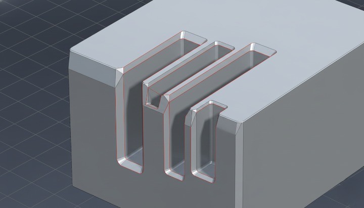
You should review pocket design because deep cavities, small radii, or narrow features heavily impact dfm design for manufacturing and tool selection. Unrealistic geometry often forces suppliers into long-reach tooling, which compromises rigidity and increases cycle time. Correctly optimized features improve machinability and enhance the part’s manufacturability meaning in practical conditions.
You can improve manufacturability by increasing radii, reducing unnecessary depth, and avoiding sharp transitions. These changes reduce the load on cutters and align with dfm principles dfm design for manufacturing recommendations. Pocket geometry often determines whether the part must go to 3-axis or 5-axis machining, influencing cost during dfm design for manufacturability reviews. Each optimization contributes to better performance, fewer setups, and a smoother design for manufacturing software workflow.
5. Confirm Material Selection for Manufacturability
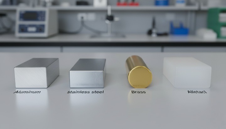
You should confirm the material because different alloys respond differently to machining, which directly affects design for manufactoring, pricing, lead time, and tool life. Aluminum, steel, brass, and plastics each require different speeds, feeds, and tooling strategies within dfm engineering meaning frameworks.
You can verify the exact alloy, hardness, temper condition, and required certifications. Ambiguous material notes slow down dfm process evaluations and complicate compliance reviews. Selecting a machinable material also strengthens your industrial design for manufacture goals and ensures alignment with what does DFM stand for in practice: reducing complexity, cost, and production risk.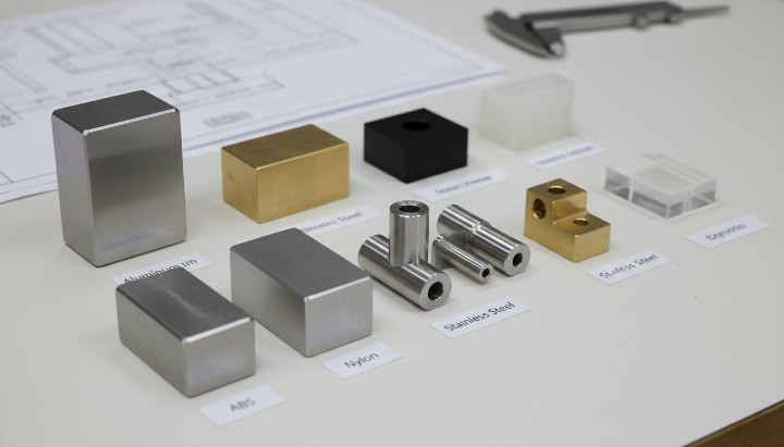
6. Review Hole Sizes, Thread Types & Drill Access
You should confirm hole dimensions because non-standard diameters disrupt efficient designing for manufacturing workflows. Suppliers prefer standard drill sizes because special tools increase machining time. Thread specifications also influence the dfm meaning engineering requirements of your part.
You can improve drill accessibility by aligning holes with natural machining orientations. This reduces secondary setups, which supports what is design for manufacturing principles and improves the reliability of your dfm analysis software evaluation. Clear notes for blind holes, bottom styles, and thread callouts reduce misinterpretation and support smoother quoting.
7. Check Part Orientation & Fixturing Feasibility
You should consider how the supplier will hold the part during machining, because fixturing directly influences design for manufacture efficiency, alignment accuracy, and cost. A thoughtful orientation supports good dfm in manufacturing practice by reducing setups and improving consistency.
You can support reliable fixturing by ensuring you have flat reference surfaces, balanced geometry, and accessible features. This helps simplify workholding strategies and aligns with design for manufacturability DFM best practices. When features are difficult to clamp or too fragile to withstand pressure, the supplier must create custom fixtures, which increases cost.
8. Surface Finish Requirements
You should confirm surface finishes early because cosmetic or functional finishes heavily influence machining speed and cost. High-precision finishes require slower feed rates and additional processing, which suppliers evaluate through the dfm manufacturing lens.
You can reduce cost by applying strict finishes only where needed. This keeps your design aligned with design of manufacturability standards and reduces unnecessary polishing or secondary operations. Clear surface specifications also improve communication and reduce errors during dfm certification or quality audits.
9. Identify Features That Increase Cost
You should identify cost-intensive features because they significantly affect the manufacturing design process and quotation accuracy. Costly features often include micro engravings, deep narrow slots, extreme tolerances, and inaccessible internal corners.
You can reduce cost by simplifying geometry where possible. This approach aligns with design for reliability and manufacturability strategies and real-world dfm examples. After reviewing each feature, you can determine whether it is functionally necessary or a by-product of design habits. Every simplification contributes to a stronger design for CNC machining outcome.
10. Verify Drawing Completeness & Correct Documentation
You should confirm that all drawings and 3D models are consistent because incomplete documentation is the most common reason RFQs stall. A complete package includes STEP/IGES files, PDF drawings with tolerances, surface notes, and revision histories. Clarity improves dfm software evaluation and supports efficient supplier communication.
You can avoid delays by checking each view, dimension, and material specification for consistency. Missing units, incorrect tolerances, or vague notes disrupt both quoting and manufacturing. Clean documentation reflects proper dfm meaning and strengthens your position as an engineering-driven buyer.
CNC Machining RFQ Package Requirements
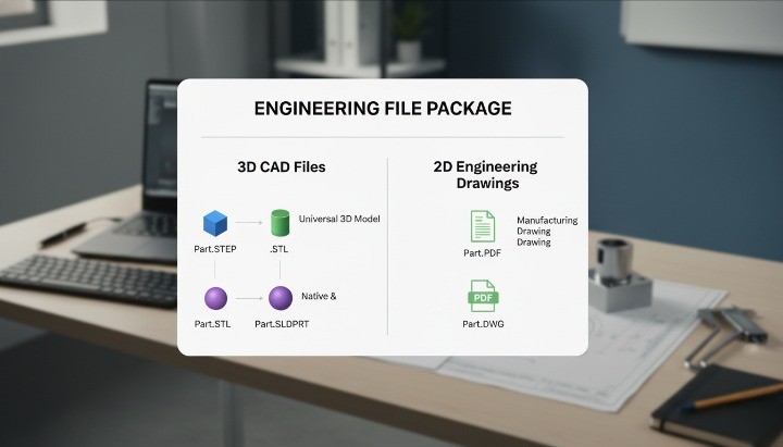
Required Engineering Files (STEP, PDF, DXF, Tolerance Drawing)
You should include complete engineering files because they provide the foundation for accurate quoting and predictable manufacturability. A supplier relies on your 3D model and drawings to conduct a reliable DFM analysis, check the geometry, and determine tool paths for design for CNC machining. These files allow the engineering team to confirm critical dimensions, machining access, and cost-driving elements before preparing your quote. Missing or inconsistent files often create delays, unclear assumptions, or avoidable engineering revisions.
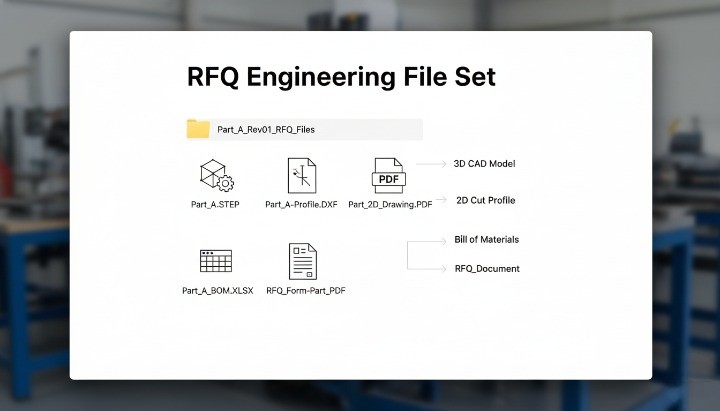
You can prepare a clean RFQ package by submitting a STEP file for 3D geometry, a PDF drawing for tolerances, and DXF files for flat profiles when needed. This complete set supports the entire design and manufacturing process and aligns with essential DFM principles used across CNC operations. Each file also helps prevent interpretation errors that could affect the final cost, machining layout, or feasibility assessment.
Recommended files to include:
• STEP (.step/.stp)
• PDF dimensional drawing with GD&T
• DXF for laser-cut or profile parts
• BOM and revision history
• Any notes related to design for manufacturability
Material & Surface Treatment Specifications
You should define materials and finishes clearly because they influence machining speed, tool choices, and overall design for machining decisions. Suppliers evaluate machinability, strength requirements, and finishing processes as part of their dfm design for manufacturing workflow. Ambiguous material notes—like “aluminum alloy” without a specific grade—cause delays and force suppliers to make assumptions that may not match functional requirements.
You can avoid misunderstandings by listing the exact alloy (e.g., 6061-T6), temper, hardness range, and any required certifications. A detailed finish specification (anodizing type, powder coat thickness, Ra surface roughness, etc.) helps clarify expectations and supports structured DFM analysis during quoting. Clear material requirements also help suppliers determine achievable tolerances and predict the final quality.
Quantity, Delivery Timeline & Inspection Requirements
You should specify quantities because machining cost is highly sensitive to batch size, setup time, and production strategy. Small batches usually cost more per unit because setups dominate the time budget, which suppliers integrate into their manufacturing DFM planning. The required delivery timeline affects machine allocation and may trigger overtime or priority scheduling, which influences pricing.
You can improve communication by listing the expected delivery date, prototype quantities, and mass-production forecast. Adding inspection requirements—such as CMM reports, PPAP Level 3, or material certificates—helps align with your quality system and ensures the supplier can meet your standards. These details are essential elements of design for manufacturing readiness before the RFQ is processed.
Packaging, Assembly or Secondary Processes
You should define packaging and secondary operations because they affect part handling, quality, and overall cost. Packaging is often overlooked, yet it plays a key role in protecting precision-machined parts from scratches or deformation. Suppliers include these requirements in their design for manufacturability cost calculations and in later stages of the manufacturing design process.
You can specify whether the parts require sub-assembly, thread installation, press-fit operations, deburring, or cleaning before shipment. Secondary processes may involve anodizing, heat treatment, grinding, or engraving. When these steps are unclear, suppliers cannot perform a complete dfm analysis or determine the full workflow sequence accurately.
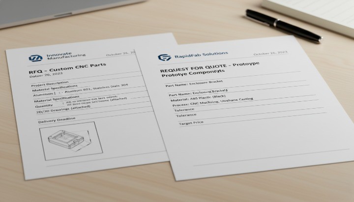
Examples of a Complete vs Incomplete RFQ
You should understand the difference between complete and incomplete RFQs because it directly shapes the speed and accuracy of supplier responses. A complete RFQ provides all the data needed to perform dfm analysis, cost estimation, and feasibility checks without guessing. An incomplete RFQ forces the supplier to pause and request clarification, which delays the entire design for manufacturing process.
You can review these examples:
Complete RFQ Includes:
• STEP + PDF drawings with GD&T
• Material and surface finish details
• Quantities and delivery expectations
• Tolerance requirements linked to function
• Notes for assembly, packaging, or secondary operations
Incomplete RFQ Lacks:
• Only a STEP file without tolerances
• Missing finish or material specifications
• No quantity or delivery timeline
• Unclear threaded holes or partial dimensioning
A complete RFQ aligns with design for manufacturability guidelines and ensures the supplier can give an accurate and fast quote.
Common DFM Mistakes That Delay CNC Machining Quotes
Over-tightening Tolerances
You should avoid unnecessarily tight tolerances because they immediately raise machining cost and extend lead time. Many engineers apply ±0.01 mm tolerances to non-functional features, which contradicts good design for manufacturability (DFM) practice. Tight tolerances affect tool selection, inspection time, and machining speed, making your supplier perform additional checks in their DFM analysis before quoting. These delays occur because suppliers must confirm whether each tolerance is functionally justified or whether it creates avoidable risks.
You can streamline the design for machining workflow by keeping only functional tolerances tight and relaxing others to general machining norms such as ±0.1 mm for non-critical surfaces. This approach aligns with established DFM principles, shortens quoting cycles, and reduces unnecessary engineering communication. It also helps suppliers optimize their machining layout and choose tools that maintain precision without slowing the entire process.
Selecting Difficult-to-Machine Materials
You should choose materials carefully because some alloys cause tool wear, slow cutting speeds, or unpredictable deformation. These issues require suppliers to adjust feeds, speeds, and fixturing methods during design for CNC machining evaluation. Alloys like 304 stainless steel or hardened steels often trigger delays because the supplier must assess whether the design is feasible or whether modifications are needed to ensure manufacturability and stable quality.
You can prevent these delays by confirming that your chosen material matches functional needs rather than habit or assumption. If you specify a difficult alloy without justification, the supplier must run additional dfm analysis steps to validate cost, cycle time, and expected surface finish. A well-prepared RFQ notes whether corrosion resistance, strength, conductivity, or temperature tolerance is the primary driver—making the design for manufacturing review more predictable and faster.
Designing 1-Piece Structures That Should Be Assemblies
You should avoid forcing everything into a monolithic structure because some geometries are not efficient or even possible to machine from a single block. Designers sometimes create deep internal channels, undercuts, or complex cavities that violate basic design for machining rules. Suppliers must then perform extended DFM analysis to determine whether 5-axis machining, EDM, or redesign is required, which significantly delays quoting.
You can simplify the manufacturing design process by splitting overly complex structures into multiple components that can later be assembled. This approach improves manufacturability, reduces material waste, and shortens cycle time. It also aligns with practical DFM principles and lowers machining risk, especially when internal features cannot be reached with standard tool paths. A multi-piece design is often cheaper, faster, and easier to inspect.
Missing Fillets & Sharp Corner Specifications
You should always specify fillets or internal radii because sharp internal corners contradict fundamental design for manufacturability guidelines. Sharp corners require extremely small end mills, which increase tool breakage risk and extend machining time. When drawings omit radii, suppliers must pause their dfm analysis to ask whether corners are functional or simply underspecified, which slows the quote.
You can improve clarity by defining internal radii that match tool availability—commonly 1 mm, 2 mm, or 3 mm depending on feature size. External corners and edges should also include chamfers or fillets to simplify the design for CNC machining pathway. When radii and corner details are clear, the supplier can produce a faster and more accurate quotation because fewer assumptions are required during the DFM check.
Submitting Drawings with Missing or Vague Data
You should avoid vague or incomplete drawings because they force suppliers to halt their evaluation until missing information is clarified. Missing tolerances, undefined threads, absent surface finish requirements, and inconsistent dimensions create uncertainty during DFM analysis. A vague drawing prevents the supplier from planning the correct machining layout and estimating machining steps accurately.
You can accelerate the quote by ensuring every drawing includes complete GD&T, thread callouts, surface roughness, reference datums, and material notes. This ensures compatibility with design for manufacturing workflows and minimizes communication loops. Clear drawings also reduce the risk of misinterpretation during production and improve the consistency of quality inspections.
![]()
How DFM Impacts CNC Machining Cost?
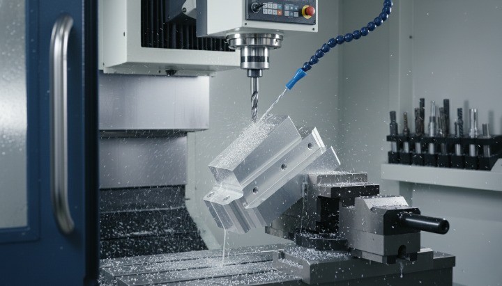
Cost Drivers in CNC Machining
You influence CNC machining cost more than you might expect because your early design decisions determine the entire design for manufacturability (DFM) pathway. The biggest cost drivers usually include material choice, tolerance levels, machining time, tool wear, and fixturing complexity. When a design includes deep pockets, sharp corners, or multiple setups, the supplier must slow cutting speeds or add specialized tooling. These factors increase machining hours, which directly affects the final price.
You can manage cost more effectively by understanding how each design feature affects manufacturability and cycle time. Materials like stainless steel or titanium require slower machining speeds, while optimized aluminum grades reduce wear and help streamline the design and manufacturing process. Tolerance relaxation on non-critical dimensions also reduces cost because it allows faster machining and simpler gauges. Every choice you make influences toolpath planning, inspection requirements, and overall efficiency during DFM analysis.
DFM Opportunities to Reduce Cost
You can significantly reduce CNC machining cost by applying practical DFM principles early in your design phase. Many savings come from simple modifications such as increasing internal corner radii, reducing the depth of pockets, or adjusting wall thickness to improve rigidity. These changes support efficient design for CNC machining, allowing suppliers to use standard tools and optimized toolpaths rather than expensive high-precision cutters.
You should also consider cost-saving opportunities related to part orientation and fixturing. When your design avoids unnecessary secondary setups, the supplier requires less time to reposition the workpiece, reducing cycle time and scrap risk. Clear GD&T and surface finish notes also reduce ambiguity during the DFM check, helping the supplier choose cost-optimized machining sequences. These improvements directly impact your per-unit cost, especially in medium- and high-volume production.
Real Examples of Cost Reduction
You can achieve meaningful savings through small design adjustments. A common example involves replacing sharp internal corners with a 2 mm or 3 mm fillet. This single change can reduce machining time by more than 30%, because it eliminates the need for tiny end mills and slow feed rates. Another example is reducing overly tight tolerances in non-critical areas. When tolerances shift from ±0.01 mm to ±0.05 mm, machining moves into a faster, more stable region of the manufacturing design process, reducing inspection requirements and scrap rates.
You may also lower cost by selecting materials better suited to the geometry. Switching from a difficult stainless steel grade to 6061 aluminum for non-corrosive environments improves manufacturability and reduces production time. These design improvements align with effective dfm design workflows and demonstrate how thoughtful adjustments deliver both performance and price advantages.
DFM Guidelines by Material Type
Aluminum (6061, 6082, 7075, 2024)
Aluminum alloys remain the most common choice for design for CNC machining, thanks to their balance of strength, cost, and manufacturability. When engineers plan a part for CNC production, aluminum often offers the best ratio of machinability, stability, and predictable performance during cutting. 6061 is the most versatile and widely used; 6082 offers better mechanical performance for structural parts; 7075 delivers aerospace-level strength but introduces higher machining difficulty; 2024 provides excellent fatigue resistance but lower corrosion resistance. Below is a concise comparison to support DFM analysis and material selection during the RFQ stage.

Aluminum Alloy DFM Comparison Table
| Alloy | Machinability (DFM Perspective) | Strength Level | Cost Impact | Typical CNC Uses |
|---|---|---|---|---|
| 6061 | Excellent manufacturability; ideal for most design for machining | Medium | Low | Housings, brackets, fixtures |
| 6082 | Good machinability; slightly tougher than 6061 | Medium–High | Medium | Structural frames, machine bases |
| 7075 | High strength, low design for manufacturability; requires stronger tooling | Very High | High | Aerospace, motorsport |
| 2024 | Good cutting performance; fatigue-resistant | High | Medium | Aerospace fittings, load parts |
Stainless Steel (304, 316, 17-4PH)
Stainless steels offer durability, corrosion resistance, and strength, but they introduce higher challenges in dfm design for manufacturing. Grades like 304 and 316 tend to work-harden, requiring controlled feeds and tooling strategies. 17-4PH offers better manufacturability than austenitic grades and produces more predictable machining results. Choosing the right grade helps control cost, tool wear, and cycle time within the design and manufacturing process.
Carbon Steel
Carbon steels provide strong, economical options for high-strength CNC parts. They machine better than stainless steel, but they still require attention to heat, burrs, and surface finish in dfm engineering. Medium-carbon grades like 1045 balance manufacturability and performance, while high-carbon grades demand precise cutting strategies to avoid tool wear. These materials suit structural and industrial applications where corrosion resistance is secondary.
Brass & Copper
Brass and copper offer exceptional machinability and thermal/electrical performance. Brass is particularly favored in design for manufacturability (DFM) because it cuts cleanly, supports tight tolerances, and reduces tool wear. Copper is softer and more ductile, which can complicate the machining layout, but it delivers unmatched conductivity. Both materials remain ideal for fittings, electrical parts, and precision components where tolerances and surface finish are critical.
Plastics (POM, ABS, PC, Nylon)
Engineering plastics play a critical role in lightweight, corrosion-resistant CNC parts. POM machines extremely well and maintains tight tolerances, making it a top choice in designing for manufacturing. ABS offers affordability and ease of machining, though it requires moderate control over heat. PC and Nylon demand careful fixturing in DFM because of their flexibility and heat sensitivity. Plastics are best suited for prototypes, gears, enclosures, and insulating components.
DFM Checklist for Multi-Axis Machining
When Your Part Requires 5-Axis?
A part requires 5-axis CNC machining when its geometry cannot be produced efficiently or accurately using standard 3-axis setups. Features such as undercuts, complex contours, compound angles, or continuous curved surfaces often demand additional tool orientation freedom. Engineers sometimes assume 5-axis is automatically “better,” but from a design for manufacturability (DFM) perspective, it should only be selected when the design cannot be simplified without losing function. Complexity without purpose increases cost, lead time, and fixturing difficulty.
In many cases, thoughtful adjustments to the machining layout—such as breaking a part into two components, adding draft, or modifying orientations—can shift a design back into a 3-axis friendly configuration. You can use this section to evaluate whether 5-axis machining is functionally required or simply a result of avoidable geometry choices.
Avoiding Unnecessary 5-Axis Costs
5-axis machining introduces higher hourly rates due to machine capability, programming time, and fixturing. A strong dfm analysis helps identify cost-reduction opportunities before the RFQ stage. Here are the leading strategies:
• Eliminate non-functional undercuts • Increase accessibility by repositioning features
• Replace sculpted surfaces with flat or stepped geometries
• Reduce compound angles unless structurally necessary
• Consider multi-part assemblies rather than complex monolithic blocks
These optimizations support the core principles of design for manufacturing, minimizing cycle time and increasing manufacturability without compromising performance.
Part Orientation & Feature Accessibility
The success of design for CNC machining heavily depends on orientation. Poor orientation can create chatter, deflection, and visibility issues that affect accuracy and surface quality.
A solid DFM check evaluates:
• Tool access and approach direction
• Required tool length and potential deflection
• Clamp and vise obstruction
• Sequence of operations
• Reorientation or multi-setup requirements
A well-chosen orientation improves the outcome of the design and manufacturing process, ensuring predictable machining and reduced scrap risk. This is also where dfm engineering software tools contribute by simulating toolpaths, identifying inaccessible areas, and highlighting geometry that violates design for manufacturability guidelines.
A simple comparison helps illustrate the impact of orientation decisions:
Effect of Part Orientation on Manufacturability
| Orientation Choice | DFM Impact | Cost Impact | Notes |
|---|---|---|---|
| Optimal single-setup orientation | High manufacturability | Low | Ideal for 3-axis machining; reduces human error |
| Requires multiple re-clamps | Moderate | Medium | Increases risk of tolerance stack-up |
| Poor access requiring long tools | Low | High | Raises tool wear, chatter, and scrap rates |
| Orientation requiring full 5-axis | Very high precision | Highest | Use only when necessary for function |
The Engineer’s Pre-RFQ Checklist
Geometry & Tolerances
Clear geometry and well-defined tolerances are the foundation of a manufacturable part. Before sending your RFQ, verify that every feature follows DFM principles, supports proper design for machining, and avoids over-engineering. Critical dimensions, fit requirements, and GD&T symbols must be consistent with function, not assumptions. Suppliers rely heavily on this information to perform an accurate dfm analysis and predict machining risks.
A practical pre-RFQ review includes:
• Confirming all radii, chamfers, and fillets are modeled—not described vaguely.
• Applying design for manufacturability (DFM) to avoid unnecessary tight tolerances.
• Ensuring there are no contradicting callouts between the model and drawing.
• Checking that the machining layout allows cutters to reach all features without violating physics.
A strong tolerance strategy improves manufacturability and reduces cost, lead time, and iterations.
Material & Surface Treatment
Material selection drives cost, tool wear, and production speed. Before submitting an RFQ, define the material grade, heat treatment, and surface finish in a way aligned with design for CNC machining. Engineers should validate that their chosen material does not conflict with machinability or tolerance needs. For example, 17-4PH in H900 condition machines very differently from annealed 6061.
A pre-RFQ material review includes:
• Selecting a material supported by your supplier’s design for manufacturing services.
• Verifying surface finish specifications reflect function, not aesthetics alone.
• Avoiding finishes that require tight sequencing without noting them—like anodizing before thread cutting.
• Ensuring the material aligns with manufacturing DFM guidelines and cost expectations.
Clear specifications minimize quoting delays and reduce supplier assumptions.
Drawings & File Format
Your RFQ must include manufacturable, organized files that support the design and manufacturing process. A universal mistake is sending only a screenshot or incomplete drawing. Suppliers perform a more accurate dfm check when files are clean, consistent, and correctly structured.
Before submission, verify:
• 3D files are STEP/IGES and represent the final design.
• 2D drawings include GD&T, tolerances, notes, thread specs, and revisions.
• Titles, units, scales, and revision codes are filled.
• No mismatch exists between 3D model and drawing annotations.
These details help suppliers interpret your intent without miscommunication and ensure a predictable design for manufacturing workflow.
Quantity, Delivery, Quality Requirements
RFQ accuracy depends on your clarity about volume, timelines, and inspection needs. Small adjustments in volume can shift machining strategies and pricing significantly, impacting both dfm manufacturing decisions and production feasibility.
Before issuing your RFQ, confirm:
•Quantity breakdowns (prototype, pilot, mass).
• Acceptable lead time ranges and delivery windows.
• Required inspection reports (FAI, CMM, material cert, RoHS).
• Packaging expectations for sensitive surfaces or tight tolerances.
Providing these details avoids re-quoting and ensures your CNC supplier proposes the right production method from day one.
Supplier Questions You Should Prepare For
Most quote delays happen because suppliers must request clarifications. Anticipating their questions accelerates response time and improves alignment with design for manufacturability guidelines.
Expect questions about:
• Missing tolerances or inconsistent callouts.
• Undercuts, deep pockets, or inaccessible features.
• Material substitutions for better manufacturability.
• Thread depth, blind hole relief, and tool access.
• Heat treatment order and finish sequences.
Being ready with answers signals that your design follows strong DFM design for manufacturing practices and increases supplier confidence in your project.
FAQs About CNC Machining DFM
How Long Does a DFM Check Take?
A typical DFM check for CNC machining takes anywhere from a few minutes to 48 hours, depending on part complexity, the completeness of your RFQ, and the supplier’s workflow. When files are clean, tolerances are clear, and design for machining principles are followed, suppliers can complete a dfm analysis quickly. More complex parts, multi-axis setups, or unclear drawings often require extended review time.
Factors affecting DFM duration include:
• Missing or vague GD&T requiring clarification.
• Difficult materials that change the design for manufacturability (DFM) approach.
• Deep pockets, undercuts, or features needing feasibility evaluation.
• Requests involving custom inspection or certification.
Providing a complete RFQ shortens the process and ensures accurate feedback.
Does Every CNC Part Need a DFM Review?
Most CNC parts benefit from at least a basic design for manufacturing review, but the depth of the check depends on the part’s function and complexity. Simple brackets or spacers may only need a quick manufacturability confirmation, while precision housings, mating components, or tight-tolerance mechanical parts often require full DFM engineering review to validate feasibility and cost.
Parts that always require DFM include:
• Components with ±0.01 mm tolerances.
•Thin-wall sections < 1 mm.
• Multi-axis geometries needing 4- or 5-axis machining.
• Assemblies with alignment-critical fits.
Skipping DFM often causes unexpected deviations, higher machining cost, or late design iterations.
What Files Are Required for an Accurate Quote?
Suppliers require clean engineering files—3D and 2D—to deliver an accurate CNC machining quote. A complete RFQ includes all data needed for design for manufacturability analysis, toolpath planning, and cost modeling. Missing files result in delays, misquotes, or manufacturing risks.
Required files include:
• 3D model: STEP/IGES of the final design.
• 2D drawing: PDF with tolerances, GD&T, threads, and notes.
• Material callouts and surface finish specifications.
• Quantity and delivery expectations.
CAD exports must reflect the true intent of dfm design, avoiding outdated or inconsistent versions.
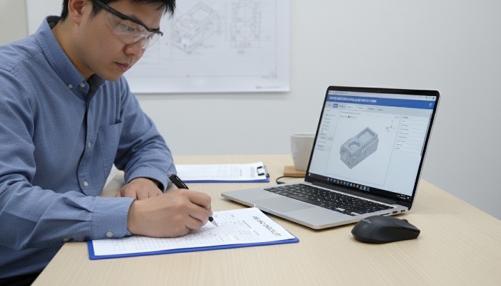
Can Suppliers Help Improve My Design?
Yes. Most CNC suppliers offer dfm feedback as part of their quoting workflow, helping refine geometry, reduce tooling difficulty, and prevent costly features. Their suggestions are grounded in practical shop-floor experience and the design and manufacturing process, ensuring your part is optimized for ease of machining and stable quality.
Suppliers often propose changes such as:
• Increasing corner radii for faster toolpaths.
• Adjusting wall thicknesses for better rigidity.
• Replacing difficult-to-machine materials with easier equivalents.
• Clarifying tolerances that appear unnecessarily tight.
Good CNC partners act as an extension of your engineering team, guiding you toward stronger design for manufacturability.
Which DFM Issues Increase Cost the Most?
The most expensive design mistakes usually involve violating basic design for machining rules or introducing features that require unnecessary setups, special tooling, or high-risk tolerances. These pitfalls force suppliers to adjust parameters, increase inspection frequency, or change machining strategies altogether.
Major cost-drivers include:
• Tight tolerances applied across the entire part.
• Deep pockets or slot depths beyond 6× tool diameter.
• Small corner radii requiring micro-tools.
• Thin walls prone to vibration or deformation.
• Complex surfaces forcing multi-axis machining.
Avoiding these issues ensures predictable pricing and aligns with strong DFM principles used across machining industries.
Conclusion
A strong DFM process helps you create CNC-machined parts that are easier to manufacture, more reliable in performance, and more cost-efficient across their lifetime. When you follow design for manufacturability (DFM)
A complete DFM mindset also strengthens decision-making around materials, tolerances, machining layout, and parts for CNC. When you address manufacturability early, your project moves faster, and your final components are easier to inspect, assemble, and scale. Strong DFM is not just a cost-control tool—it is a discipline that improves product reliability and accelerates the entire design and manufacturing process.
Get a Free DFM Review Before Your CNC Machining Quote
If you want a reliable manufacturing partner who can support DFM analysis, optimize your model, and help you avoid costly design pitfalls, our engineering team at HM is ready to help. You can send your 3D models, drawings, or RFQ package, and we will perform a free DFM check to highlight risks, machining challenges, cost drivers, and improvement opportunities.