


Choosing between a chamfer and a fillet in CNC design directly affects cost, manufacturability, and part performance.
Engineers and procurement teams face this decision on almost every machined housing, bracket, shaft, or die-cast component they release for production, yet edge details often stay vague in drawings and RFQs. That gap turns into avoidable machining time, quality risk, and frustrating back-and-forth with suppliers.
In this guide, you’ll see clear rules for chamfer vs fillet, practical DFM tips, and real-world scenarios so you can send cleaner drawings, cut machining cost, and reduce surprises during prototype and production builds.
Clear Definitions – Fillet, Chamfer, Bevel & Edge Break in CNC Design
What Is a Fillet in Engineering and CNC Machining?
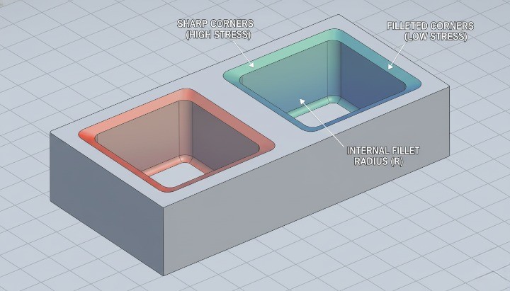
A fillet is a rounded transition between two surfaces. In CNC machining, it reduces sharp corners and spreads stress across a curved profile. Fillets improve fatigue performance, support load paths, and help prevent crack initiation, which is why you see them in structural brackets, shafts, and housings. Machinists produce fillets with end mills that have matching tool radii. Larger radii reduce machining time, while small radii require slow cutting and specialized tools. For this reason, standard radii often cost less and produce more consistent parts.
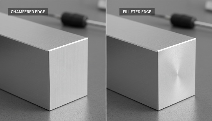
What Is a Chamfer and How It Differs from a Bevel
A chamfer is a straight, angled cut that removes a sharp edge. It usually appears at 45 degrees, although shops can machine other angles when needed. A bevel is similar but typically larger and often part of a functional geometry such as a weld prep or an angled mating interface. In CNC work, chamfers guide assembly, eliminate burrs, and create clean visual lines. They are faster to machine than fillets because a chamfer mill follows a simple path and requires no corner rounding. When you want cost efficiency and clean edges, a chamfer is often the practical choice.
Edge Break, “Break Sharp Edges” and Deburring Notes Explained
“Break sharp edges” is a general instruction used across mechanical drawings. It tells the machinist to lightly remove burrs without applying a defined chamfer or fillet. Most workshops treat this note as a small hand-deburred edge, often between 0.1–0.3 mm. This note works for cosmetic or non-functional edges, but it lacks precision. If you need a consistent angle or radius, you should specify a chamfer or fillet dimension. When drawings mix “break edges” with explicit callouts, shops may hesitate, leading to clarifications and delays. Clear, consistent notes reduce ambiguity and help maintain uniform appearance across batches.
How Chamfers and Fillets Appear in CAD Models and 2D Drawings
In CAD, you usually model fillets and chamfers directly so they carry into STEP files and machining simulations. On 2D drawings, chamfers appear as size × angle (such as 1.0 × 45°), while fillets appear as a radius (R2, R5, etc.). If the 3D model shows radii but the drawing does not, machinists may choose their own interpretation, which reduces design control. The best practice is to keep CAD and drawings aligned, especially when parts need repeatable performance or tight assembly fits. Using standard notation from ASME Y14.5 or ISO 2768 improves clarity and ensures the supplier follows your intent.
Clear Definitions – Fillet, Chamfer, Bevel & Edge Break in CNC Design

What Is a Fillet in Engineering and CNC Machining?
In engineering, a fillet is a rounded transition between two surfaces, usually at an internal or external corner. You typically see fillets where a vertical wall meets a floor, where a shaft shoulder steps down, or where a rib blends into a base. In CNC machining, fillets reduce stress concentration, improve flow of forces through the part, and make toolpaths smoother and more stable. Standards such as ASME Y14.5 and ISO 13715 recognize fillets as common features on mechanical drawings, especially when they influence fit or function.
On a CNC mill, a fillet usually comes from the radius of the cutting tool. A 6 mm end mill will naturally leave a 3 mm internal fillet where it turns a corner. If you call out a smaller radius than the tool can reach, the programmer must select a smaller cutter, add extra passes, or create 3D toolpaths. That adds time, increases risk of chatter or breakage, and often raises your machining cost. This is why fillet size should follow tool size whenever possible, rather than the other way around.
Fillets also influence assembly and performance. A well-chosen fillet radius helps bearings seat correctly, prevents stress risers at shaft shoulders, and reduces crack initiation points under fatigue loading. Many fatigue handbooks show that a simple fillet can cut stress concentration factors by 20–50% compared with a sharp corner on the same geometry. When you combine this with good material selection and surface finish, you gain a large improvement in durability at very little extra cost.
From a design point of view, keep fillet usage intentional. Use larger, tool-friendly radii in non-critical areas to speed up machining. Reserve special radii and tight tolerances for interfaces that truly control fit, sealing, or fatigue behavior. This mindset lets you keep the benefits of fillets without turning every corner into a cost driver.
What Is a Chamfer and How It Differs from a Bevel?
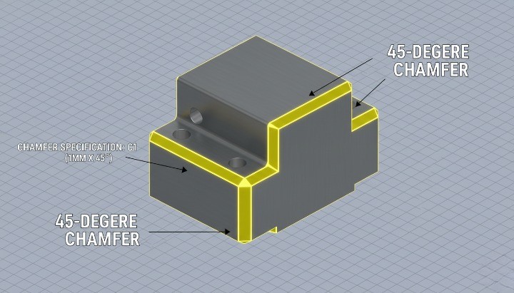
A chamfer is a straight, angled cut that replaces a sharp 90° corner. In CNC design, you usually express it as a length and angle (for example 1×45°) or as a single dimension when the angle is implied (commonly 45°). Chamfers help parts assemble more easily, remove razor-sharp edges, and give visible surfaces a clean, deliberate look. They are common on hole entries, panel edges, covers, and any feature that needs a lead-in or safer handling.
A bevel is a more general term for any angled surface that is not perpendicular to the main faces. In metalworking, engineers often use “bevel” for larger, functional angle cuts, such as weld preparations or sloping faces on structural components. All chamfers are technically bevels, but in CNC part drawings, “chamfer” usually refers to small edge treatments, while “bevel” often points to a larger, structural feature. Using the right word helps your supplier understand if you are talking about a small edge break or a major angled surface.
From a machining perspective, chamfers are usually simpler and faster to cut than fillets. A single chamfer mill or a tool with a 45° tip can run around the edge in one pass at relatively high feed rates. This is why designers often switch from fillets to chamfers on external edges when they want to reduce cycle time but still avoid sharp corners. You still protect the operator’s hands, support assembly, and give a neat visual finish, while keeping tooling and programming straightforward.
In design reviews, it helps to decide early whether a feature is a cosmetic chamfer, a functional chamfer, or a larger bevel. Cosmetic chamfers can share common sizes across many parts, which simplifies programming and inspection. Functional chamfers around holes or mating edges might need tighter control, but you can still standardize angles to common tooling such as 45° or 30° to keep costs predictable.
Edge Break, “Break Sharp Edges” and Deburring Notes Explained
On many CNC drawings you will see notes like “Break sharp edges”, “Deburr all edges”, or “E0.2–0.5”. These notes tell the machinist to remove sharp edges without giving a precise chamfer or radius on every single line. The goal is simple: prevent cuts during handling, reduce the risk of chipping, and avoid tiny burrs that interfere with assembly. International standards such as ISO 13715 give guidance on how to specify and interpret edge conditions, so both designer and manufacturer understand how much material to remove.
An “edge break” usually means a very small chamfer or radius, often in the range of 0.1–0.5 mm on metal components. The machinist may use a deburring tool, a countersink, a file, or abrasive methods, depending on the part and process. You do not control the exact geometry, only the fact that the edge should not remain sharp. This keeps programming simple and avoids the need to fully model or dimension every single minor edge in CAD.
However, you should not rely on generic “break all edges” notes in areas where geometry truly matters. Sealing surfaces, precise fits, and functional interfaces need explicit control of radius or chamfer size. If you leave those to general deburring, you risk inconsistent results between batches or between suppliers. The best practice is to use a combination of both approaches: explicit edge callouts on critical features, and global break-edge notes for all other edges.
When you prepare drawings for RFQ, take a moment to align edge notes with your quality expectations. If all edges must be free of burrs but only a few need controlled geometry, say so clearly. This reduces back-and-forth with your CNC supplier, protects important interfaces, and still allows them enough freedom to choose efficient deburring methods for non-critical areas.

How Chamfers and Fillets Appear in CAD Models and 2D Drawings?
In modern CAD systems such as SolidWorks, Inventor, or Fusion 360, fillets and chamfers usually sit at the end of the feature tree as “cosmetic” or finishing operations. Designers often add them late in the modeling process, after extrusions, cuts, and patterns are complete. This workflow feels convenient, but it can also hide manufacturing complexity, because a single “Fillet All Edges” feature may create dozens of costly toolpath segments during machining.
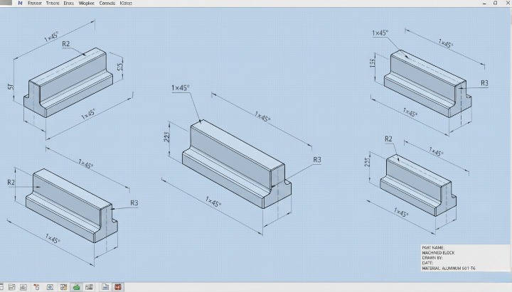
On 2D drawings, fillets appear as R dimensions (for example R3, R0.5), while chamfers appear as length × angle or a single chamfer size where the angle is implied. You may also see collective notes such as “Unless otherwise specified, all external edges C0.5” or “All internal corners R2 min.” These notes help standardize design language and reduce the number of individual dimensions on the sheet, as long as they match what you actually modeled in 3D.
A common pain point in CNC projects comes from mismatches between CAD and drawing. The 3D model might include small fillets for aesthetic reasons, while the 2D drawing only shows a few functional radii and a generic edge-break note. CAM programmers usually trust the 3D geometry, so they will cut every modeled fillet unless you agree otherwise. To avoid surprises, keep your 3D model and drawing consistent: either remove non-essential fillets from the model, or clearly mark them as “for reference only” when you want your supplier to skip them.
When you send STEP files for quoting, you also send your fillet and chamfer choices, even if you never mentioned them in the drawing. That is why edge design should be part of your early DFM checklist, not an afterthought. Before you export, scan your model for very small radii, inconsistent chamfer sizes, and sharp internal corners that do not match realistic tool diameters. A short review at this stage often saves hours of machining time and reduces change requests once your CNC partner starts programming the part.
Cost Impact – How Chamfers and Fillets Influence CNC? Machining Price
Well-chosen chamfers and fillets can reduce CNC machining cost, but unnecessary or poorly defined edge details often do the opposite. Edge geometry directly affects toolpaths, cycle time, setups, inspection workload, and even scrap rate, so it becomes a real cost lever instead of a “cosmetic” choice. When you treat edge design as part of your cost strategy, you protect both your budget and your lead time.
Toolpaths, Cycle Time, and Machine Load for Chamfers vs Fillets
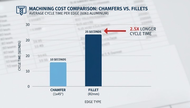
From a machining point of view, a chamfer is usually simpler and faster than a fillet. A standard 45° chamfer can often be cut with a single pass using a chamfer tool, while a fillet normally needs a ball end mill or a smaller radius tool and multiple passes to generate the curved profile. More passes mean higher cycle time and higher spindle load, which both show up in your part price.
Cycle time also changes with how many edges you detail. If every edge on a housing, bracket, or cover has a specified fillet radius, the CAM programmer must create additional toolpaths and the operator must run more operations. In contrast, if only functional or safety-relevant edges get defined and the rest use a simple “break sharp edges” note, you reduce the amount of machining required. This approach keeps cost under control while still protecting assembly and handling.
Machine load matters too. Small fillet radii require small tools, and small tools need lower feed rates to avoid breakage. That slows the whole program, especially in hard materials. Larger, more standard radii or simple chamfers allow the use of stiffer tools and more aggressive feeds. When you multiply this over hundreds or thousands of parts, the difference in cycle time per piece becomes a meaningful cost factor.
Setup, Tooling, and Programming Time Behind Edge Features
Every unique edge requirement can add work before the first chip is cut. Dedicated chamfer tools, extra ball end mills, or special radius cutters need to be selected, loaded, and measured. If your design calls for several non-standard radii or different chamfer angles on the same part, the programmer may need multiple tools and multiple operations to satisfy the drawing, which increases both setup time and programming time.
Programming complexity drives engineering cost. CAM programmers must define specific strategies for small radii in tight corners, long chamfers along complex contours, or blended surfaces. If your edge callouts are inconsistent or more detailed than necessary, you pay for that extra programming time whether you see it itemized or not. In many shops, this cost is rolled into the per-piece price or a one-time NRE charge.
Tooling cost is another consideration. Standard chamfer tools (for example 45°) and common ball end mills are inexpensive and always available. However, special profiles, unusual angles, or very small radii may require custom tools or more frequent replacement. That extra cost is usually spread across the batch and reflected in the quoted price. By staying close to standard chamfer angles and common cutter sizes, you reduce tooling overhead without compromising function.
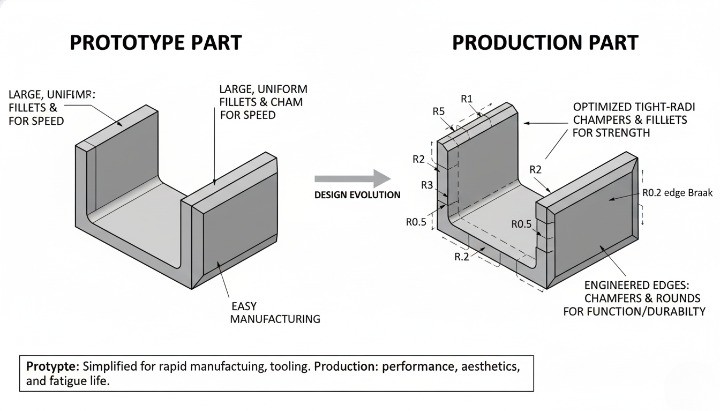
Prototype vs Production Runs – When Edge Details Hurt or Help Cost?
Edge strategy should not be the same for prototypes and for long-term production. In early prototype CNC machining, you often want speed and flexibility above everything else. At this stage, extensive filleting on non-critical edges or complex blended transitions mostly slow down machining and make it harder to iterate. For prototypes, a simple set of chamfers and basic fillets at structurally critical locations usually gives you the right balance between function and cost.
When you move into stable production, the picture changes. Repeating the same part over many batches means the initial programming and setup cost is amortized over a larger volume. Well-designed fillets can then help in two ways: they reduce stress concentrations in long-life components and can also support smoother toolpaths, especially when high-speed machining strategies are used. In this phase, small investments in better edge design often reduce long-term cost through fewer failures, less rework, and smoother assembly.
There is also a transition phase between prototype and production where many teams get caught. If you lock in a prototype design that uses over-detailed edges, every later production batch inherits that cost. A better approach is to review chamfers and fillets before final release. You can relax non-essential edges, standardize radii, and remove decorative details that add no functional value, so your production pricing stays competitive without a full redesign.
Hidden Costs: Deburring, Inspection, Rework, and Scrap Risk
Even when the main toolpaths look simple, edge choices create hidden costs in finishing and quality control. Every sharp or poorly controlled edge requires deburring. When drawings do not clearly distinguish critical edges from cosmetic ones, operators may spend unnecessary time hand-finishing the entire part to avoid complaints. That manual labor adds cost and can also introduce variation between batches.
Inspection effort increases as you add detailed callouts. If many chamfers and fillets have tight size tolerances or specific angles, quality teams need more measurements per part and more time per inspection report. In high-mix environments, this extra work reduces throughput and pushes up quality-control cost. By keeping tolerances realistic and focusing on edges that really affect function, you reduce inspection load without compromising reliability.
Edge design can also change your scrap rate. Very small radii or fragile features at edges are more likely to chip, especially in hard materials or when parts see secondary operations like heat treatment or surface finishing. Each part scrapped at final inspection represents lost material, machining time, and capacity. When you simplify edge features and avoid fragile, non-essential details, you lower the risk of scrap and protect your overall project margin.
Manufacturability – DFM Principles for Chamfers and Fillets
The way you design chamfers and fillets directly determines how easy your part is to machine. Good edge design reduces setups, avoids tiny tools, and keeps cycle time predictable. Poor edge design forces special tooling, risky toolpaths, and unstable machining conditions that drive cost and delay delivery.

Tool Access, Cutter Diameter, and Minimum Fillet Radius
Tool access is the first manufacturability filter. If the cutter cannot reach an edge in a stable posture and with enough clearance, that feature becomes expensive or impossible to machine.
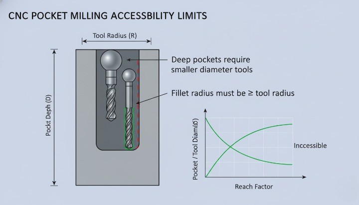
For fillets, the minimum fillet radius must be larger than the cutter radius you expect your supplier to use. Very small internal radii (for example 0.5 mm in a deep pocket) force tiny end mills, low feed, and frequent tool breakage. As a simple rule of thumb, try to keep internal fillet radii ≥ 1/3 of pocket depth where the geometry allows it. This gives enough space for a realistic tool diameter and healthy cutting parameters.
Chamfers usually give more freedom. A simple 45° chamfer on an external edge can be cut with a standard chamfer mill in one pass. That is why a chamfer is often cheaper than a small internal fillet when the functional requirement allows it. However, if you specify narrow, deep chamfers inside pockets, the machinist may need a small included-angle tool or custom setup, which cancels the cost advantage.
When you design, think in terms of standard tool families:
-
End mills with common diameters (e.g., 3, 6, 8, 10, 12 mm).
-
Chamfer tools at 45° or 30°.
-
Corner-radius end mills with standard radii.
If your fillet or chamfer forces a non-standard cutter, expect higher cycle time and longer lead time.
Deep Pockets, Internal Corners, and Hard-to-Reach Edges
Deep pockets and tall walls are where chamfer vs fillet choices really influence manufacturability. A deep slot with sharp internal corners is already challenging. If you then specify tiny fillet radii at the bottom, the setup becomes even more fragile. The tool must be long, slender, and slow, which increases chatter and tool wear.
In many cases, you can relax the fillet requirement or use a larger blended radius at the bottom of the pocket. This allows the machinist to use a shorter, stiffer tool and higher feed rates. If functional requirements demand a tight internal corner, consider whether wire EDM, broaching, or design modification is more realistic than forcing a very small milling cutter into a deep cavity.
Hard-to-reach edges often appear behind ribs, under overhangs, or between closely spaced bosses. Here, a simple edge break or micro-chamfer may be more realistic than a full fillet. A note like “Break sharp edges 0.2–0.5 mm” gives your supplier freedom to deburr by hand or with a small tool, instead of programming a full 3D fillet path in a cramped area.
You should also avoid mixing many different chamfer sizes and fillet radii in one tight area. Each unique size might require a separate toolpath or even a different tool. By standardizing radii and chamfers where possible, you make deep and internal features much easier to machine at scale.

Effects on Fixturing, Number of Setups, and Process Stability
Every time the machinist needs to clamp your part in a new orientation, you add a setup. More setups usually mean more cost, more chance for error, and more variation in edge alignment. Chamfer and fillet placement can either simplify or complicate fixturing.
If you put critical fillets and chamfers on faces that are already accessible from the main setup, the supplier can machine them in the same program. If you place important edges on awkward back faces, they may need an extra setup or even a custom fixture. That extra setup is not only cost; it also increases the risk of registration errors between features.
Well-chosen chamfers can actually improve process stability. For example:
-
Chamfers on support surfaces can help a part seat consistently in a fixture.
-
Chamfers on clamping faces reduce high local stress and minimize marring.
-
Small edge breaks on datum features help avoid burrs that interfere with repeatable location.
Fillets at the base of ribs, bosses, and bearing seats also contribute. They reduce stress concentration in the part, which matters for performance, and they also reduce stress in the material during machining. A part with generous internal fillets typically responds better to clamping and vibration, which supports stable cutting and consistent quality.
When you review your design for manufacturability, ask:
-
Can all critical edges be reached in one or two logical setups?
-
Are any fillets or chamfers placed on faces that require a special fixture only for that purpose?
-
Do edge features help or hinder the way the part is held and referenced?
If the answer looks negative, you have a good opportunity to adjust the edge strategy and make the whole process more robust.
Material-Specific Considerations (Aluminum, Steel, Stainless, Zinc)
Different materials react very differently to small tools and intricate edges. The same fillet that is easy in aluminum can be painful in hardened steel or sticky stainless. That is why material and edge design must be considered together.
For aluminum alloys, larger fillets and simple chamfers are generally easy to machine. Aluminum cuts freely and allows higher spindle speeds. Designers can often specify a slightly larger radius on internal corners without any downside. This supports strong, lightweight designs and also keeps machining time reasonable.
Carbon steels and alloy steels are less forgiving. Small radii with high hardness will slow down cutting speeds and put more stress on the cutting edge. If you call out a very tight fillet on a steel bracket or shaft shoulder, the machinist may need premium tools, reduced feed rates, or additional finishing passes. That combination quickly increases cost. It is often better to use a standard radius that matches common tool sizes, unless your load case truly requires a smaller corner.
Stainless steels add another challenge: work hardening and heat generation. Here, narrow chamfers and tiny fillets can turn into hotspots. Tools rub instead of cutting cleanly, which shortens tool life. If you design stainless parts with many precise small edge features, try to limit the number of sizes and prioritize only the edges that matter functionally.
Zinc and aluminum die-cast components with secondary CNC machining form a special category. The casting already contains many fillets defined by the mold. Post-machining usually focuses on functional edges and surfaces. In this scenario, you should design edge treatments so that machined chamfers and fillets complement the cast geometry, rather than fight it. For example, use machined chamfers to clean up interfaces and sealing edges, while leaving non-critical cast fillets as they are.
Notes for Milled, Turned, and Die-Cast Parts with Secondary CNC
For milled parts, chamfers and fillets appear on pockets, slots, outer profiles, and mounting faces. Here, simple chamfers on external edges are cheap and reliable. Internal fillets should match standard tool radii wherever possible. Three-axis milling can handle most cases if the edges are visible from one or two main orientations. When you add complex 3D fillets on multiple faces, you often move into long 3D toolpaths or even 5-axis setups. That change should be a conscious decision, not an accident from a “smooth everything” modeling habit.
Turned parts follow slightly different rules. On shafts, bushings, and housings, chamfers and fillets define how parts assemble and how loads flow from one step to the next. A small fillet at a shoulder can dramatically reduce stress concentration, while a short chamfer at the end of a shaft helps bearings and seals slide into position without damage. Because lathes handle chamfers and radii efficiently with standard inserts, you can often specify simple, consistent edge conditions along the length of the part without major cost impact.
Die-cast parts with secondary CNC machining demand clear separation between cast edges and machined edges. The casting design includes generous fillets to encourage good flow and solidification. Machining then refines only those features that matter for fit, sealing, or alignment. In this mixed process, your drawings should state which edges are defined by the casting and which are machined. Cast fillets should stay relatively large and organic, while machined chamfers and radii remain simple and consistent to keep CNC time under control.
In all three process families, the same principle applies:
-
Use chamfers for easy deburring, assembly lead-in, and visible edges that do not carry high stress.
-
Use fillets where you need smooth load transfer, fatigue resistance, or a defined transition radius.
When you align these rules with realistic tool access, standard cutter sizes, and simple setups, chamfers and fillets stop being cosmetic details and become a deliberate DFM tool that keeps your CNC projects on time and on budget.
Functional Performance – Strength, Stress & Assembly Behavior
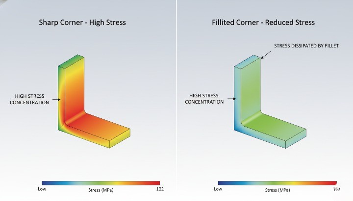
Stress Concentration – When Fillets Are Structurally Mandatory
Fillets matter whenever geometry changes and load flows through that region. A sharp corner concentrates stress, while a fillet spreads it. In load-bearing parts, a fillet is often not an option but a structural requirement.
In simple bending or tension, a square shoulder can raise local stress by several times compared with a filleted transition. That means higher risk of crack initiation, fatigue failure, or plastic deformation, especially under cyclic loading. If the section changes thickness, or a rib blends into a wall, a fillet lets the load “turn the corner” more gradually. You get a smoother stress field, longer fatigue life, and more stable performance.
For most CNC-machined parts that handle significant load, use fillets at:
-
Shaft shoulders and step transitions.
-
Bosses and ribs connecting to base plates or housings.
-
Internal corners in brackets and frames.
In many cases you can keep cost under control with standard tool-friendly radii. For example, matching fillets to half of a common end mill diameter avoids tiny cutters. You maintain structural benefit without pushing machining time through the roof.
When Chamfers Improve Assembly, Lead-In, and Handling Safety
Chamfers shine where the designer cares more about assembly, fit, and handling than raw strength. A small chamfer guides mating parts, protects edges, and removes burrs that could cut operators. In these cases, a simple chamfer is often the most cost-effective choice.
On shafts, pins, and fasteners, a chamfer acts as a lead-in. Assemblers do not need to “hunt” for the hole, so insertion is faster and less likely to damage the bore. On covers and housings, chamfers around bolt holes help center screws and reduce cross-threading. This brings down assembly time and reduces rework.
From a safety perspective, sharp edges on handheld parts or exposed corners are rarely acceptable. A modest chamfer (for example 0.5–1.0 mm at 45° on aluminum parts) breaks the edge and reduces cut risk. You improve ergonomics and user perception with very little extra machining time.
Chamfers also help when parts will be coated, painted, or anodized. They reduce the chance of flaking at corners and give coatings a more even build. In many visible assemblies, a consistent chamfer standard creates a clean visual language across components.
Edge Design for Fatigue, Impact, and Vibration Performance
Fatigue, impact, and vibration expose weaknesses in geometry that static tests often hide. Repeated load cycles “find” every stress raiser in the part. Here, fillets at critical transitions are one of the most effective and economical design tools.
Under fatigue loading, cracks usually start at surface imperfections or geometric discontinuities. A sharp internal corner, a keyway root, or an abrupt change in shaft diameter becomes a preferred crack site. Adding a properly sized fillet lowers the stress concentration factor and delays crack initiation. Even a small, tool-friendly radius can significantly improve fatigue life.
For impact and shock loads, the situation is similar. The more abrupt the geometry, the more local energy concentrates in one spot. Fillets spread that energy and reduce peak local stress. Chamfers, by contrast, mainly change contact conditions and handling, not the internal stress path.
Vibration adds another layer. Edges near natural frequency modes see repeated micro-strains. Fillets at those hot spots can reduce peak stresses and stabilize long-term performance. This is particularly relevant for rotating parts, robotic joints, and structural brackets in dynamic assemblies.
A simple decision rule helps:
-
Use fillets where the part carries cyclic or shock loads through a change in section.
-
Use chamfers where the main need is entry, clearance, or safe handling, and local stress is low.
Visual and Aesthetic Factors on Visible CNC-Machined Surfaces
Edge design also shapes how a part looks and feels in the hand. For visible components, buyers and end users notice this immediately. A consistent edge strategy can signal quality and engineering care before anyone reads a drawing.
Fillets create softer, organic transitions. They often suit consumer-facing products, medical devices, or enclosures that users touch regularly. Combined with bead blasting or fine machining, large fillets can make a machined part look close to a cast or molded part. This is useful when you want a premium feel or want to align with an existing design language.
Chamfers read as sharper and more technical. They catch light, define edges clearly, and emphasize geometry. On industrial parts, control panels, or precision fixtures, uniform chamfers convey accuracy and robustness. They also highlight interfaces, making it obvious where components should meet.
You can also mix the two:
-
Larger external fillets on hand-contact areas for comfort and safety.
-
Chamfers on functional features like holes, slots, and interfaces for clarity and assembly guidance.
Whatever you choose, keep it consistent across the assembly and across product families. Define a standard set of chamfer sizes and fillet radii in your design rules. That way, visual quality improves while machining stays efficient, because your supplier can standardize tools and programs.
Practical Rules – When to Choose Chamfer vs Fillet

Fillet vs Chamfer on Transitions, Shoulders, Bosses, and Ribs
On transitions between sections (for example, a shaft step, a rib base, or a boss), a fillet is usually the default choice. It spreads stress, avoids sharp corners, and helps the cutter move smoothly. A chamfer can still work, but it behaves more like a geometric cut than a stress-relief feature.
When a step carries load, supports a bearing, or sees repeated bending, a fillet almost always makes more sense than a chamfer. The rounded shape reduces stress concentration and improves fatigue life. In contrast, a chamfer at a loaded step looks clean but keeps a sharp change in direction in the stress flow.
For bosses, ribs, and gussets, small fillets at the base help both CNC machining and casting. The cutter can follow a smoother path, and the structure becomes less prone to cracking. A chamfer in these areas is usually cosmetic and may even create small pockets where stress can build.
You can use chamfers on external transitions when the feature is not load-bearing and you mainly care about deburring or assembly lead-in. However, if in doubt and the area carries load, prefer a fillet and only trim it with a chamfer if you need a lead-in for assembly.
A simple rule of thumb for transitions, shoulders, bosses, and ribs:
-
Use fillets for load paths, fatigue-sensitive regions, and internal geometry.
-
Use chamfers when you only need to break the edge or guide a part during assembly.
-
Keep fillet radii compatible with standard tool sizes to avoid custom cutters.
-
Do not mix random radii and chamfers in the same functional region without a clear reason.
External Edges, Interfaces, and Mating Features in Assemblies
On external edges and interfaces, chamfers often win on practicality and cost. They make parts easier to handle, reduce the chance of cutting hands, and help components slide into position during assembly. A simple 0.5–1.0 mm 45° chamfer around a housing opening can save time on the line and reduce cross-threaded fasteners.
Fillets on external edges mainly serve appearance and comfort. They feel smoother, look more “finished”, and can make a premium part stand out. However, they often take longer to machine than a straightforward chamfer, especially on corners that require 3D toolpaths or small ball-end mills.
On mating features between two parts, think about how the parts come together. A chamfer on the male feature and a sharp or lightly broken edge on the female feature helps with alignment and avoids edge chipping. Fillets on mating surfaces can help with stress and sealing, but they may reduce effective contact area or interfere with gasket seats if not planned carefully.
When external edges sit under covers or inside hidden areas, there is rarely a reason to specify complex fillets. A global “break sharp edges” note or small chamfer is usually enough. Save detailed fillet and chamfer callouts for interfaces that actually matter for fit, sealing, alignment, or safety.
Practical guidance for external edges and interfaces:
-
Use chamfers for assembly lead-in, screw entry points, door or cover openings, and visible but non-critical edges.
-
Use fillets where hands frequently touch the part, where you need a soft visual look, or where external stress concentration is a concern.
-
Avoid full 3D decorative fillets unless you accept the extra cycle time.
Holes, Countersinks, Threads, and Access Points Around Edges
Around holes and threads, the chamfer vs fillet question becomes a functional topic. Most engineers use chamfers to help fasteners start smoothly and to remove burrs. A small chamfer on a tapped hole also protects the first thread from damage.
Fillets around holes usually appear in two situations. The first is around a heavily loaded hole, such as a bolted joint on a structural bracket. A fillet where the hole blends into a pocket or rib reduces local stress. The second is when a designer wants to improve flow or sealing around a port, especially in fluid or pneumatic components. In those cases, a smooth radius can help.
For countersinks and counterbores, standard chamfer angles align with screw head geometry. There is rarely a benefit to a fillet in those regions. Instead, a clean chamfer or countersink ensures good seating and torque transfer. A simple “chamfer to remove burr” around clearance holes usually meets both cost and quality goals.
Access points, such as tool access holes, cable pass-throughs, or inspection ports, benefit from chamfers because they guide tools and reduce wear on cables or hoses. If the edge sees significant rubbing or impact, a fillet can provide a softer interface and extend life.
Practical rules for holes and access features:
-
Use chamfers at screw holes, tapped holes, and clearance holes for entry and deburring.
-
Use fillets around structural holes or ports where stress, flow, or sealing performance matters.
-
Keep chamfer sizes standardized across a part to simplify tool selection and programming.
Prototyping vs Locked Production – How Edge Strategy Evolves
Edge strategy should evolve from simple and flexible in prototypes to optimized and standardized in production. During early design phases, large decorative fillets and complex chamfers only add time and cost without real value. In many cases, a global “break sharp edges” note and a few functional fillets are enough for prototypes.
As you move toward a locked production design, it makes sense to refine the chamfer vs fillet choices based on test results, fatigue data, and assembly feedback. At this stage, you can decide which edges truly need defined fillets, which areas need chamfer lead-ins, and where a simple deburr is sufficient. This step often removes dozens of unnecessary edge callouts and trims cycle time.
Production parts also benefit from standardization. Using the same fillet radii and chamfer sizes across families of parts allows your CNC partner to reuse tools and programs. That reduces setup time and helps keep long-term costs predictable. In contrast, random edge sizes in every new part lead to more tool changes and more programming work.
A practical way to guide this evolution is to treat edges as design variables, not fixed decorations. During prototyping, document where operators struggle with assembly, where parts crack, and where cosmetic complaints appear. Then carry those insights into the final chamfer vs fillet decisions. You end up with edges that exist for a reason, not just for the sake of a clean CAD model.
Dimensioning Strategy – Cost-Effective Radii, Angles & Tolerances
Standard Chamfer Sizes and Angles Compatible With Common Tools
A chamfer that looks simple on a drawing can still create cost if it does not match common tools. For cost control, the goal is to speak the same language as standard cutters and CNC programmers. That means using sizes and angles that most shops already keep in their tool holders.
In most CNC shops, you will typically see:
-
45° chamfer mills as the default choice
-
30°, 60° and 90° tools in some cases
-
Metric or inch tip diameters in standard steps
As a practical rule, try to:
-
Use 45° chamfers unless there is a strong functional reason not to
-
Dimension the chamfer as X × 45° (for example, 0.5 × 45° or 1.0 × 45°)
-
Avoid very small, non-standard chamfer lengths that require fragile tools
You also decide what you actually care about. For many edges, a global note such as “0.2–0.5 mm × 45° chamfer where shown” gives the machinist flexibility to stay within a safe, low-cost range. Reserve tight chamfer tolerances for edges that affect fit, sealing, or assembly jigs.
If your team uses drawing standards such as ISO 13715 for edges, keep them consistent across parts. Clear and repeatable edge notes reduce back-and-forth during RFQs and manufacturing.
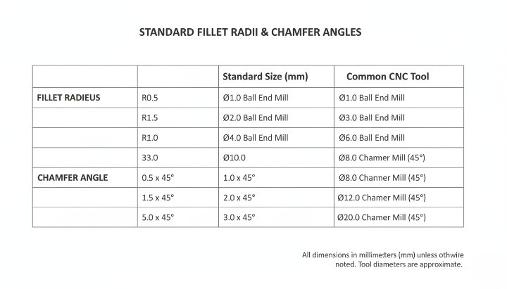
Choosing Fillet Radius Based on Tool Diameter and Feature Size
A fillet radius always links back to a specific tool diameter. If the radius does not match a practical tool, the shop must slow down or use special cutters. That is where Chamfer vs Fillet becomes a cost question, not just a design preference.
A simple checklist when you pick a fillet radius:
-
Check the smallest practical end mill that can reach the corner
-
Keep R = 0.5 × tool diameter as a starting point where possible
-
Avoid radii that require tools under 2–3 mm in production unless absolutely necessary
For example:
-
If a 6 mm end mill is the smallest tool that can reach the area, a 3 mm fillet is a natural choice
-
A 0.8 mm fillet in the same corner forces a much smaller cutter, slower feeds, and more risk of tool breakage
You also want the fillet radius to make sense relative to wall thickness and part size. On a large aluminum housing, a 0.5 mm fillet does not add much stress relief or manufacturability. A radius of 2–3 mm often gives a better balance between strength, flow of stress, and machining speed.
When in doubt, you can mark:
-
Minimum radius required (for example, “R ≥ 2 mm”) instead of a single fixed value
-
Functional features as “critical radius” and allow tolerance or freedom on others
This approach gives your CNC partner room to choose the most efficient tool while still meeting design intent. For more detailed background on tolerances around holes and fits, you can link to a dedicated tolerance guide on your own site, such as a CNC machining tolerance article.
Chamfer vs Radius – When a Simple Chamfer Is Cheaper Than a Fillet?
In many edges, a chamfer provides enough function at lower cost than a fillet. Machinists can cut chamfers in a single, straightforward toolpath. A small internal fillet usually needs 3D contouring or special tool motion, which adds time.
A quick comparison helps your team decide:
| Design Choice | Typical Use Case | Machining Effort | Cost Impact (Prototype & Low Volume) | Notes on Edge Behavior |
|---|---|---|---|---|
| Small internal fillet (R ≤ 1 mm) | Stress relief in highly loaded features | Needs small tool, slower feeds | Higher | Best reserved for truly critical features |
| Medium fillet (R 2–3 mm) | Transitions on ribs, steps, and pocket corners | Uses common tool, moderate effort | Moderate | Good mix of strength and machinability |
| Simple chamfer (0.5–1.0 × 45°) | Edge break, deburring, lead-in for assembly | Single pass with chamfer mill | Lower | Often enough for handling and assembly edges |
| Edge break note only (“break edges”) | Non-critical, cosmetic-only edges | Done during deburring | Lowest | No exact size control, just safe to handle |
In non-critical edges, a chamfer or even a “break sharp edges” note gives:
-
Safe handling during assembly
-
Lower risk of chipping
-
Clear improvement in perceived quality
Where stress and fatigue are not critical, choose a chamfer instead of a fillet to avoid extra toolpaths. You keep performance where it matters and remove cost where it does not.
Avoiding Over-Tolerancing on Non-Critical Edges
Many drawings carry tight tolerances on every edge by default. This creates unnecessary cost and inspection effort, especially for chamfers and small fillets. From a DFM point of view, only a small portion of edges truly need tight control.
You can split edges into three groups:
-
Function-critical edges: fits, sealing surfaces, precision locators
-
Assembly and handling edges: chamfers for insertion, safety, deburring
-
Cosmetic-only edges: non-contact external corners and faces
For the first group, you define exact dimensions and tolerances. You might keep tolerance grades aligned with ISO 2768 fine or similar standards. Here, the extra control links directly to product performance.
For the second and third groups, you allow more freedom:
-
Use wider tolerances or ranges (for example, 0.2–0.5 mm chamfer)
-
Use general edge notes instead of individual callouts on every line
-
Avoid applying ±0.05 mm tolerances to chamfer length unless absolutely required
Over-tolerancing also affects inspection. Every extra tight feature pushes the shop to spend more time on measurement and documentation. By relaxing non-critical edges, you give your supplier space to optimize process settings and keep price under control.
If your organization relies on a general tolerance block, review it with your CNC partner. You can adjust default edge tolerances for machined parts to match your real functional needs. This small step alone often removes cost without changing any CAD geometry.
Explicit Edge Callouts vs Global “Break Sharp Edges” Notes
You decide how much control you want to keep at edge level. Explicit callouts and global notes both have a role in Chamfer vs Fillet decisions.
Explicit edge callouts work best when:
-
The edge defines a fit or sealing line
-
The edge interacts with a mating component, gasket, or bearing
-
The chamfer or radius impacts assembly direction or tool access
In these cases, you specify:
-
Exact size and angle, for example “0.8 × 45° chamfer”
-
Exact radius with tolerance, for example “R2 ± 0.1”
A global note such as “Break sharp edges 0.2–0.5 mm” fits non-critical edges. The shop will treat them during deburring with a file, wheel, or brush. You get safe, non-sharp parts without extra dimensioning work.
A balanced strategy usually looks like this:
-
Use explicit callouts only where edge geometry has a clear functional role
-
Use global edge notes for everything that is only about comfort, handling, and appearance
-
Keep the number of different edge specifications low to simplify programming and inspection
This balance gives you control where you need it and speed where you do not. It also reduces the risk of contradictions between CAD, 2D drawing, and machinist interpretation. For teams that work with multiple suppliers, a clean edge strategy also supports consistent quality across vendors.
Edge Design for Different CNC Manufacturing Scenarios
Prototype CNC Machining – Fast Iterations and Flexible Edge Choices
In prototype CNC machining, edge design should support speed and learning, not perfection. At this stage, you usually validate fit, function, assembly, and broad aesthetics. You rarely need every tiny chamfer and fillet exactly as in the final drawing. For prototypes, keep chamfer vs fillet choices simple, standard, and easy to machine.
A practical strategy is to use standard chamfers on external edges and only add fillets where they clearly affect strength or assembly. You can often accept a global note such as “break sharp edges” instead of dimensioning every edge, especially for one-off or very low-volume builds. This reduces CAM work, avoids unnecessary tool changes, and helps you get parts faster without sacrificing learning value.
For internal corners and pockets, choose larger, tool-friendly radii that match common endmill diameters. If you already know your future production process, align prototype radii with those production tools. That way, you avoid redesign later. When in doubt, ask your CNC partner which fillet radii and chamfer sizes allow them to run your parts on standard tooling and fixturing.
For prototypes, you can also relax cosmetic edges. Many teams accept slightly sharper corners in non-contact areas, as long as there is no safety risk. Save the fully refined fillet strategy for the design freeze. The goal in prototyping is to learn quickly with minimal cost, not to over-optimise every edge.
• Use standard chamfers (for example 0.5–1.0 mm at 45°) on external edges.
• Use fillets only where they affect function, sealing, or strength.
• Prefer global edge break notes over fully detailed edge drawings.
Suggested image placeholder: prototype housing with simple chamfers and a few functional fillets. Alt text: “Prototype CNC aluminum housing with standard chamfers and minimal functional fillets.”
Production CNC Machining – Repeatability, Automation, and Deburring Strategy
In production CNC machining, edge design becomes a lever for repeatability and throughput. You now care about cycle time, tool life, automation, and how easily operators can control variation. Well-standardised chamfers and fillets reduce scrap and make production more predictable.
For repeated batches, align chamfer sizes and fillet radii across families of parts. This allows your supplier to reuse tools and CAM templates, and to combine parts in the same setup when possible. A consistent edge strategy also makes automated deburring and brushing more effective, which cuts manual labor and variation.
Your chamfer vs fillet choice should reflect the production deburring method. If your supplier uses tumbling, brushing, or robotic deburring, they may recommend certain edge sizes and radii that produce stable results. Very small or inconsistent edges are hard to verify and tend to generate rework. Standardisation is often more valuable than pushing for exotic edge profiles.
In production, you also define clearly which edges are critical, functional, or purely cosmetic. Critical edges may need precise chamfers or fillets and formal dimensional checks. Cosmetic edges often only need a safe edge break and visual inspection. This tiered approach helps your CNC partner focus inspection time where it matters and keep overall cost under control.
• Standardise chamfer sizes and fillet radii across part families. • Align edge design with deburring and finishing strategy. • Define clear inspection rules for critical vs cosmetic edges.
Suggested image placeholder: multiple identical housings in a production tray, showing consistent chamfered edges. Alt text: “Production batch of CNC machined aluminum housings with uniform chamfers on all external edges.”
Die Casting + Secondary CNC Machining – Cast Fillets vs Machined Chamfers
When you combine die casting with secondary CNC machining, edge design sits at the intersection of tooling design and machining economics. Cast parts usually rely on generous fillets and radii to support metal flow, reduce porosity, and extend tool life. Secondary CNC operations then refine only the critical features.
A common strategy is to design cast fillets on most transitions and reserve machined chamfers for interfaces, sealing faces, and assembly points. This approach uses casting to create smooth, strong transitions, while CNC machining only touches edges that directly influence fit, sealing, or user contact. This combination often provides the best balance between strength, cost, and appearance.
You also need to think about machining allowances. Cast fillets may be slightly larger or less accurate than final requirements, so you leave enough stock on critical surfaces. After CNC, those edges carry the final chamfer size or fillet radius. Close coordination between your casting supplier and CNC machining partner avoids conflicts where a cast fillet makes tool access difficult or forces extra setups.
For visible parts, you can use casting to generate smooth, flowing fillets on major transitions and then apply small chamfers on functional edges like mounting holes or connector ports. This keeps cosmetic quality high without driving machining time through the roof. When you evaluate quotes, compare the full chain: casting tool design + secondary machining + finishing, not just the unit price.
• Use cast fillets for strength, flow, and tool life; machine only where function requires it. • Define machining allowances so cast fillets and machined edges work together. • Coordinate casting and CNC DFM reviews to avoid accessibility issues.
Suggested image placeholder: die-cast housing with large cast fillets and locally machined chamfered ports. Alt text: “Die-cast aluminum housing showing cast fillets on ribs and machined chamfers on connector openings.”
High-Reliability Applications (Automotive, Medical, Robotics, Energy)
High-reliability applications place stricter demands on edge design. You are no longer optimising only for ease of machining. You must also control stress, fatigue, safety, cleanliness, and regulatory expectations. In this context, fillets often become mandatory on highly stressed transitions, while chamfers play a critical role in assembly guidance and safe handling.
For parts exposed to cyclic loads, impact, or vibration, avoid sharp internal corners wherever possible. Even small fillets greatly reduce stress concentration compared with a sharp transition. In safety-critical components, engineering teams often specify minimum fillet radii based on FEA, fatigue data, or industry standards. They may also require full traceability on edge-related design changes.
At the same time, medical and robotics applications care about cleanability and snag-free handling. Filleted edges reduce debris traps and make cleaning or sterilisation easier. Chamfers help guide mating parts and tools without catching cables, tubing, or gloves. For energy and heavy-duty systems, chamfers on external edges improve handling safety for technicians and reduce the risk of edge damage during installation.
In these sectors, you should document chamfer vs fillet choices with more detail than in simpler industrial designs. That means clear 2D notes, references to applicable standards, and alignment with any test protocols. Work with suppliers who can provide process capability data for the features you care about most. The priority shifts from pure cost to a controlled, predictable behaviour over the full life of the product.
• Use fillets systematically on highly stressed transitions and load paths.
• Design chamfers for safe assembly, tool access, and cleanability.
• Document edge requirements in line with industry or regulatory standards.
Suggested image placeholder: high-reliability CNC part (e.g., robotic joint or medical component) with highlighted fillets and chamfers on key interfaces. Alt text: “High-reliability CNC component showing filleted internal transitions and chamfered external edges for safe assembly.”
Common Design Mistakes with Chamfers and Fillets (and How to Avoid Them)

Tiny Non-Standard Radii That Force Special Tools and Extra Cost
One of the fastest ways to increase CNC machining cost is to specify very small, non-standard fillet radii. A corner with a 0.2 mm or 0.5 mm radius looks harmless in CAD, but on the shop floor it can force the programmer to use tiny end mills, slower feeds, and extra tool changes. Cycle time goes up, tool life goes down, and the quote reflects that. In many cases, the part does not gain any real performance benefit from such aggressive radii, especially on non-critical internal corners and pockets.
You reduce this risk when you match fillet radii to standard tool diameters used on typical 3-axis or 4-axis machining centers. For example, if the shop commonly runs 6 mm or 10 mm cutters for roughing and finishing, fillets that work well with those tools keep the process efficient. You still get smooth stress transitions and easier chip evacuation, but you avoid unnecessary micro-tool work. As a simple internal rule, you can mark any radius below a certain threshold as “critical only if justified by function” and challenge it before releasing the drawing.
A good practice is to build a small internal table of “preferred radii” for your parts portfolio. Start from the most common cutter diameters and back-calculate reasonable radii for pockets, ribs, and internal corners. When engineers want to deviate from that list, they should specify a reason: mating part geometry, sealing function, optical alignment, or other proven needs. This keeps creative freedom where it matters, but blocks cosmetic or habitual micro-radii that only increase machining cost and scrap risk.
If you are not sure whether a radius is realistic, you can send your model to your CNC supplier and ask directly which radii work best with their current tool library. That short discussion usually reveals easy simplifications, and the long-term cost savings can be significant over hundreds or thousands of parts.
Unmachinable or Hard-to-Access Internal Corners and Edges
Another frequent problem is internal corners or edge blends that are technically machinable but extremely hard to reach. Deep pockets with narrow openings, undercuts that require special tooling, or blended surfaces hidden behind ribs all create headaches in CAM programming. The result is often a mix of long tool overhangs, reduced cutting parameters, and additional setups. Even if the first batch passes inspection, repeatability can suffer because the process is not robust.
You can spot these issues early by thinking from the cutter’s point of view. A simple question helps: “Can a real tool actually see this edge in a straight line?” If the answer is no, you probably force the shop to use extended tools or special holders. These add deflection and vibration, which reduce accuracy. When you combine deep features with aggressive fillets or chamfers, the problem becomes worse. In a 3D model everything looks clean; in the machine, metal removal becomes slow and uncertain.
To avoid this, try to simplify access paths for the tool. Widen the pocket entrance, straighten one wall where possible, or move a rib slightly so a standard end mill can pass freely. If you need an internal fillet for strength, consider increasing its radius to match a larger tool that can reach the bottom in fewer passes. For some parts, you may even split the geometry into two components that bolt together, instead of fighting with one very complex monolithic block. The extra assembly step can be cheaper than extreme machining.
When you send your RFQ, it helps to highlight any deep pockets or critical internal edges in a short note. Invite your supplier to propose alternate radii, chamfers, or local geometry changes that improve machinability. This turns a potential problem into a design partnership and often uncovers improvements that lower cost without compromising function.
Conflicting CAD vs Drawing Edge Specifications and Notes
A classic source of confusion is inconsistent edge information between the 3D model and the 2D drawing. The CAD model may show generous fillets, while the drawing adds a global note like “BREAK ALL SHARP EDGES 0.2 × 45°” or a specific chamfer callout on the same edge. Programmers then need to decide which source to trust. In the worst case, different teams read the data differently, and you receive parts that technically follow one document but fail your internal interpretation.
The problem escalates when multiple revision cycles add new notes but old ones stay in the title block. For example, the drawing might still contain a general “break edges” note, while the latest revision moved to explicit fillet dimensions on most corners. If no one cleans up the legacy note, it remains ambiguous whether the shop should still break unlisted edges or leave them sharp. This type of conflict slows RFQ evaluation, invites extra emails, and can delay production.
A better approach is to treat the model and drawing as a consistent pair. Decide which document is the authority for geometry and which holds the tolerances and notes, then stick to that choice. Many teams use the 3D model as the master for shape, and the 2D drawing for dimensions, tolerances, and surface finish requirements. In that scenario, any change to chamfers or fillets must appear in both places before release. A short internal checklist before issuing a new revision helps catch mismatches.
You also reduce risk by avoiding overlapping notes. If you list explicit chamfers and fillets for most edges, consider limiting global notes to truly generic deburring instructions, such as “Remove sharp edges; maximum edge break 0.2 mm unless otherwise specified.” This still gives machinists guidance for safety and handling, but keeps clear priority on the explicit callouts tied to functional edges.
Misuse of Fillets on Non-Functional or Hidden Areas
Many parts leave the CAD system with fillets on almost every edge, simply because default modeling habits favor rounded corners. On the screen the part looks smooth and refined, but on the shop floor every extra fillet becomes another feature to machine. Hidden surfaces, internal pockets that never see a mating part, or structural ribs buried deep inside a housing often carry fillets that add little or no functional value. Yet they force the machinist to adjust toolpaths and reduce stepdowns to respect those curves.
You can often remove or simplify fillets in non-functional areas without sacrificing performance. If a hidden rib only sees compressive load, a sharp or lightly broken edge may work just as well as a full-radius fillet. In many applications, the as-milled surface from a standard end mill already creates a small natural radius at the toolpath cusp. That effect reduces stress concentration compared to a mathematically perfect sharp corner, even when you do not model a fillet. In those cases, specifying a precise radius is unnecessary.
A practical way to clean this up is to mark edges in three categories during design reviews: function-critical, user-facing, and hidden/non-critical. Function-critical edges include transitions at high-stress locations or interfaces to seals, bearings, and precision fits. User-facing edges are visible or handled by operators, so they may need a consistent fillet or chamfer for safety and aesthetics. Hidden/non-critical edges can often keep only a generic “break edges” note instead of detailed fillet dimensions. This framework keeps the drawing focused and the process efficient.
If you work with multiple suppliers, you can also ask them to point out any fillets they see as unnecessary during DFM review. They know where their machines naturally leave a small radius and where a fully defined fillet forces extra operations. Their feedback helps you update future designs so you reserve detailed fillet specifications only for edges that truly require them.
Over-Specifying Cosmetic Edges as Critical Features
Another common mistake is to treat purely cosmetic edges as if they were critical functional features. For example, a decorative chamfer on the front face of a cover might carry a tight dimensional tolerance and a low surface roughness requirement, even though it does not interface with any other component. Machinists then have to slow down feeds, add extra inspection steps, and sometimes even rework minor visual imperfections that do not affect the product’s performance at all.
You can avoid this by drawing a clear line between functional specifications and cosmetic expectations. Functional specifications belong on the drawing with explicit dimensions, tolerances, and surface finish symbols. Cosmetic expectations, such as “no sharp burrs on visible edges” or “consistent visual chamfer around the front face,” can be handled with general notes or a separate workmanship standard. When your team treats every edge as a critical feature, you pay for inspection and rework that your end customer may never see.
It also helps to align cosmetic requirements with the chosen finishing process. If the part will receive bead blasting and anodizing, some minor tool marks on a cosmetic chamfer may disappear or become negligible after finishing. In that case, overly strict roughness values on the raw machining operation do not make sense. Instead, you can set realistic expectations on the final finished surface and let the supplier tune the machining and finishing sequence to hit that combined target.
Communicating Edge Requirements in RFQs and DFM Reviews
What to Include in Drawings, Models, and STEP Files for Edges?
Clear communication of chamfer and fillet requirements starts with the technical package you send with your RFQ. Your supplier should see the same edge intent in the 2D drawing, 3D model, and STEP file — with no guesswork. That is the only way to quote accurately and avoid surprises during machining.
For CNC work, a good baseline is a fully dimensioned 2D drawing plus a clean 3D model. The drawing carries tolerances, edge notes, and surface finish; the 3D model carries geometry. If you use general tolerance standards such as ISO 2768 for linear, angular, and chamfer tolerances on broken edges, state this clearly in the title block so your supplier knows which default limits apply.(source:iso.org) This avoids long strings of repetitive tolerances and keeps the drawing readable.
At edge level, you have three main tools:
-
Explicit edge callouts (e.g. “2× 0.5 × 45° chamfer”, “R2 fillet”)
-
General notes (e.g. “Break sharp edges 0.2–0.5” or “Deburr all edges”)
-
Global standards in the title block or notes (e.g. “General tolerances ISO 2768-m”).
Use explicit callouts for edges that matter functionally or for assembly guidance. Use general notes only for non-critical edges where exact size is not important. When you rely on a global note such as “Break sharp edges,” consider also giving a range, for example 0.2–0.5 mm, so the shop knows what “break” means on your project.
In your STEP file, keep the model simple and consistent with the drawing. Avoid embedding small decorative fillets that you do not mark on the drawing and do not actually need. These features push toolpath time up but do not add value. If the 3D model shows a radius and the drawing does not, many shops will assume the model wins and machine the radius anyway, raising cost for no functional reason.
When you use GD&T or geometrical tolerancing on edge-related features (for example, flatness of chamfered faces or runout of shoulders with fillets), follow recognized standards such as ISO 1101.() This helps your supplier interpret the symbols correctly and avoids local “dialects” of tolerancing that lead to misinterpretation.
[Image suggestion: zoomed-in engineering drawing corner showing chamfer callouts, global “break sharp edges” note, and ISO 2768 reference in title block. Alt text: “CNC drawing example showing chamfer and fillet edge notes and general tolerance standard.”]
How to Prioritize Critical vs Cosmetic Edges for Your CNC Supplier?
Not all edges are equally important. If you treat every chamfer and fillet as critical, you will pay for it in unit price and lead time. A better approach is to clearly separate functional edges from cosmetic or safety edges and tell your supplier where they can safely optimize.
Functional edges include:
-
Contact interfaces between mating parts.
-
Transitions where stress concentration matters (shoulders, roots, load paths).
-
Edges that affect sealing, alignment, or precise positioning.
-
Edges used for location during assembly or measurement.
Cosmetic or safety edges include:
-
External corners customers see but that do not carry load.
-
Edges that simply need to be non-sharp for handling.
-
Hidden edges inside enclosures where the exact chamfer size is not important.
A simple way to communicate priority is to label edge groups on the drawing:
-
“Critical edge – maintain specified chamfer/fillet and tolerance.”
-
“Functional edge – keep feature, ±0.1 acceptable unless otherwise noted.”
-
“Non-critical edge – break sharp edges 0.2–0.5, supplier discretion.”
You can use color codes in a marked-up PDF or a short legend in the notes. This takes only a few minutes and gives the CNC supplier confidence to simplify toolpaths or combine operations on non-critical edges, which reduces cost. In many projects, this kind of clarity saves more than a few percent on pricing because the shop spends less time over-machining purely cosmetic corners.
For recurring parts, you can also build an internal design guide that defines standard edge treatments per product family. Then you only mark exceptions on the drawing. Over time, this reduces noise around edge communication and gives both your design team and your suppliers a shared language.
Where it makes sense, you can link readers to a broader design-for-manufacturing checklist, such as your internal RFQ guidance or a public resource like a CNC machining RFQ checklist page on your site, to give context on how edge priority fits into the entire part specification package.
Questions to Ask in a DFM Review About Chamfer vs Fillet Choices
A structured DFM discussion turns edge design from a cosmetic detail into a cost lever. Good questions signal to your supplier that you are open to optimization, not just enforcing a frozen drawing. That usually leads to better pricing and fewer issues during ramp-up.
Useful questions include:
-
“Which chamfers or fillets on this part drive the most machining time?” This pushes the machinist to reveal where small radii, deep corners, or 3D blends are hurting cycle time.
-
“Are there any radii that force special tools or extra setups?” If a single non-standard R0.8 corner requires a small cutter and a new setup, you may decide to increase it to a more common value or convert it to a chamfer.
-
“Can any of these decorative fillets be converted to simple chamfers or edge breaks?” This question often frees up several minutes of machining per part, especially on housings and covers.
-
“Are there edges where we can loosen tolerance or surface finish without risk?” The operator sees where they are spending time to hit tight numbers that do not influence function.
-
“Do you see any unmachinable or risky internal corners?” Here you want the shop to highlight potential tool breakage, chatter, or access problems so you can adjust the design early.
During a DFM call or email exchange, keep the tone collaborative. Make it clear that you are not asking for shortcuts on critical features, but you actively want to trade unnecessary edge complexity for robustness and cost savings. Over multiple projects, this builds trust: shops are more willing to share process insights when they know you will act on them instead of insisting on every tiny fillet in the original CAD.
You can also capture these questions into a short internal checklist that your design team runs before sending out RFQs. This keeps chamfer vs fillet decisions intentional rather than accidental, especially when multiple engineers work on the same product line.
Sharing Tolerance and Finish Flexibility to Reduce Cost
Edge specification is not only about geometry. Tolerance ranges and surface finish requirements around chamfers and fillets have a direct impact on tooling, inspection time, and scrap rate. If you communicate where you are flexible, your supplier can often reduce cost without touching critical performance.
For general edges that are not sealing or locating surfaces, you can:
-
Refer to a general tolerance class such as ISO 2768-m or -c instead of calling ±0.02 mm everywhere.()
-
Specify a range for broken edges (e.g. 0.2–0.5 mm) rather than a fixed dimension.
-
Use descriptive roughness targets (e.g. “Ra ≤ 3.2 µm for visible faces, Ra ≤ 6.3 µm elsewhere”) instead of overly fine finishes on all surfaces.
On function-critical edges, state clearly which elements are non-negotiable and which are open for discussion. For example:
-
“Fillet R3 at shoulder is for stress reduction, radius size no smaller than R2.5.”
-
“Chamfer 1.0 × 45° for assembly lead-in; angle can vary ±5° if length stays within ±0.1.”
This kind of statement gives the machinist practical room to choose standard tools and feeds, while still protecting your design intent. You stay in control of function, but you release control of unnecessary detail.
It also helps to align finish expectations with use case and industry norms. A medical housing or a visible consumer-facing enclosure may justify tighter finish and visually consistent edges. An internal bracket in a machine frame usually does not. Being explicit about where cosmetic quality matters avoids a common problem where shops over-polish or over-machine non-visible corners because the drawing is silent.
Machined Aluminum Housing: Full Fillets vs Simplified Chamfer Strategy
On a typical CNC-milled aluminum housing, engineers often start with generous internal fillets and fully rounded external edges for better stress distribution and “premium” appearance. This looks good in CAD, but it can easily add several minutes per part in machining time. Every extra tool change and 3D contour pass directly increases cost, especially in low to medium volumes.
A cost-focused version of the same housing usually keeps functional fillets only where they are structurally or geometrically required—for example at internal corners that must match a mating part or reduce stress around a fastener boss. Non-functional outer edges move to simple 45° chamfers produced with a standard chamfer mill. These can often be machined in the same setup, with a single pass around the perimeter.
In practice, this means:
-
Keep internal fillets where a mating PCB, gasket, or cover needs clearance or stress relief.
-
Use chamfers on visible edges, lid interfaces, and screw access holes where they mainly guide assembly and remove sharpness.
-
Relax radii on non-critical edges to match standard cutter sizes instead of “nice-looking” but non-standard values.
When teams apply this balance, it is common to see 10–20% reductions in cycle time on complex housings, while functional performance and aesthetics remain fully acceptable for industrial equipment or enclosures.
Turned Shaft Shoulder: Sharp Corner vs Filleted Transition
On a turned shaft, the corner at a shoulder step can become a classic fatigue failure point. A pure sharp corner (theoretically zero radius) gives the highest stress concentration. It may pass initial testing, but under cyclic loading, micro-cracks tend to start exactly at this point. A small fillet at the shoulder usually offers a huge gain in fatigue life for almost no machining penalty.
From a turning perspective, adding a fillet at the shoulder often requires only a tool nose radius that is already present on a standard insert or a simple programmed contour. In many cases, the cost difference between a sharp theoretical corner and a modest radius (for example 0.5–1.0 mm) is negligible. The real constraint comes from mating part geometry: bearings, seals, or gears may require a relief or groove to clear that radius.
A practical approach is:
-
Start with a small, standardized fillet radius that matches common insert nose radii.
-
Coordinate with bearing or gear suppliers to confirm acceptable shaft shoulder radii and relief features.
-
Mark this fillet as critical on the drawing if it directly affects fatigue life or alignment.
By doing this, you align the design with both standard turning practice and better fatigue performance, instead of forcing a nominally “sharp” corner that the tool cannot realistically reproduce and that adds hidden risk in the field.
Structural Bracket: Optimized Radii for Strength, Weight, and Cost
Consider a machined or machined-from-extrusion structural bracket that connects a motor, gearbox, or actuator to a frame. Engineers often want high stiffness, low weight, and good fatigue performance. The first instinct is to add large fillets everywhere and remove every sharp edge. This can work, but it sometimes leads to unnecessary 3D machining and extra toolpaths that do not add real structural benefit.
An optimized design usually starts with a simple, prismatic shape that fits standard stock sizes. Fillets then appear in a targeted way:
-
Larger radii where ribs meet the base plate or vertical walls, to reduce stress and improve load transfer.
-
Standard radii at pocket corners that match available end mill diameters, avoiding tiny custom tools.
-
Chamfers instead of fillets for outer edges that only need lead-in and safe handling.
To make this trade-off visible, teams sometimes compare two models:
| Design Aspect | “Fillet Everywhere” Bracket | Optimized Fillet & Chamfer Bracket |
|---|---|---|
| Internal pocket corners | Small custom fillets, non-standard sizes | Radii match standard cutter diameters |
| Outer edges | Fully rounded | Simple 45° chamfers on non-critical edges |
| Machining strategy | More 3D contouring, extra tools | Mostly 2.5D operations, fewer tool changes |
| Structural performance | Good | Comparable, with fillets used only where load is high |
| Typical unit cost | Higher (longer cycle, more tools) | Lower (shorter cycle, easier programming) |
The key lesson is simple: use fillets where they genuinely carry load or smooth stress paths, and use chamfers or broken edges where you only need safe handling and easy assembly. This keeps weight and stiffness under control without paying for decorative radii that do not improve real-world performance.
Die-Cast Part with Post-Machining: Using Cast Fillets + Machined Edges
Die-cast parts add another layer to the chamfer vs fillet discussion. A well-designed die-cast component already includes generous cast fillets and smooth transitions to help metal flow, avoid hot spots, and reduce shrinkage porosity. After casting, CNC machining usually targets functional faces, holes, and critical interfaces.
In this scenario, the most cost-effective strategy often uses:
-
Fillets formed by the die in non-critical areas and around ribs, bosses, and thick-to-thin transitions.
-
Machined chamfers only on edges that affect assembly, sealing, or alignment, such as gasket surfaces, dowel holes, or screw entrances.
-
Minimal additional fillets from machining, limited to features that truly need higher precision than the casting can provide.
If the designer adds many small machined fillets on surfaces that are already filleted by the die, the supplier must create extra toolpaths to “clean up” areas where the casting is already functional. This adds cost without solving a real problem. A better tactic is to respect the cast geometry and only overlay machining where tolerances, flatness, or surface finish are critical.
For example, a die-cast motor housing might keep all internal rib fillets as-cast, while the mounting feet and shaft bore receive light machining with a combination of face milling, boring, and simple chamfers. The result is a part that leverages the efficiency of die casting and only uses CNC time where it actually improves fit, alignment, or long-term reliability.
This combination of cast fillets and selective machined chamfers is one of the most effective ways to control total cost while still meeting demanding dimensional and functional requirements in automotive, robotics, and industrial equipment.
Pre-RFQ Design Checklist for Chamfers and Fillets
A clear checklist before you send an RFQ saves you from hidden cost, change requests, and vague “this edge is hard to machine” feedback. Use the list below to sanity-check your chamfers and fillets so your supplier can quote accurately and manufacture reliably.

Edge Priorities – Which Features Truly Matter Functionally
Start by ranking edges by function instead of treating every corner the same. You want your supplier to see, at a glance, which edges matter for performance and which are mainly cosmetic.
You can group edges into three simple buckets:
-
Critical structural edges – transitions near high loads, stress raisers, fatigue-sensitive zones.
-
Critical interface edges – edges that affect sealing, assembly fit, alignment, or ergonomics.
-
Non-critical / cosmetic edges – edges whose main job is appearance or safe handling.
For each part, ask yourself:
-
Which edges protect against fatigue or impact? These typically need fillets with defined radii.
-
Which edges guide assembly, mating, or insertion? These often benefit from chamfers or lead-ins.
-
Which edges only need to be safe to touch? These usually only need “break sharp edges” or a small generic chamfer.
A simple way to make this actionable is to add a short note in the drawing legend:
-
“Only edges marked A/B/C are functionally critical; all others may be broken 0.2–0.5 mm.”
This tells your CNC partner exactly where to focus their best tools and their tightest control, and where they can keep things simple.
Cost Levers – Where to Relax Radii, Angles, and Tolerances
Before you issue the RFQ, walk through your chamfers and fillets and deliberately look for “over-designed” edges. Every non-standard radius, unusual angle, or tight tolerance is a lever that shifts cost up or down.
Use this quick checklist:
-
Can I standardize angles to 45° or 30° for chamfers instead of odd values?
-
Can I round radii up to match common tool sizes (e.g., 1 mm, 2 mm, 3 mm, 5 mm)?
-
Do all edges really need ±0.05 mm, or can non-critical ones be ±0.2 mm or even “reference only”?
-
Are any tiny fillets (e.g., R0.2, R0.3) actually necessary, or are they a CAD default that drives tiny tools and extra time?
A simple comparison table helps you think in terms of cost levers rather than just geometry:
| Design Choice | Typical Impact on Cost | Recommended Practice |
|---|---|---|
| Standard chamfer angles (30°, 45°) | Easier programming, standard tools | Use wherever function allows |
| Non-standard angles (17°, 23° etc.) | Extra programming and tool setup | Avoid unless function clearly demands it |
| Fillet radius matches tool size | Faster machining, fewer passes | Align radii with common cutter diameters |
| Very small radii (≤ R0.3) | Tiny tools, low feeds, higher breakage risk | Use only for true functional or cosmetic reasons |
| Tight tolerances on all edges | More inspection, slower machining | Tighten only on critical edges |
| Mixed tolerances by priority | Lower overall cost at same functional performance | Make critical vs non-critical explicit |
If you can relax even 20–30% of your edge specifications, you often see a noticeable drop in quoted price, especially on complex housings and brackets.
Manufacturability Requirements – Tool Access, Setups, and Materials
Next, review the drawing as if you were the machinist. Ask yourself whether a real tool can reach each edge with a sensible tool length, approach angle, and number of setups.
Use this pre-RFQ manufacturability checklist:
-
For deep pockets and internal corners, have you chosen a minimum fillet radius that a common end mill can reach without extreme stick-out?
-
For edges at the bottom of deep channels, can the tool approach without colliding with walls or clamps?
-
Are there chamfers or fillets that require an extra setup only for one or two edges? If yes, can you simplify them?
-
Does the material (aluminum vs hardened steel vs stainless) make certain tiny chamfers or radii unrealistic in normal production?
You can phrase manufacturability expectations in the notes section:
-
“Tool access priority is given to edges marked A/B; non-critical internal corners may be broken by tool radius.”
-
“Internal corner fillets R2–R3 acceptable unless otherwise specified.”
Also think about your material choice. Stainless steel, for example, punishes very small tools and large chamfer depths because of tool wear and heat. If you know you are using a tough material, you should be even more careful about tiny radii and decorative edges.
Documentation – Are Edge Notes Clear, Consistent, and Unambiguous?
Finally, make sure your documentation tells one clear story. Conflicting or vague edge notes are one of the fastest ways to create scrap, delays, and back-and-forth emails.
Run through this documentation checklist before sending the RFQ:
-
Do global notes (“Break sharp edges”, “Chamfer 0.5×45° unless noted”) contradict any local callouts?
-
Are chamfer and fillet symbols used consistently in every view and detail section?
-
Does the 3D model match the 2D drawing for all visible chamfers and fillets?
-
Are there any legacy notes from previous revisions that no longer apply?
Where possible, keep the structure simple:
-
One global rule for non-critical edges (e.g., small break or generic chamfer).
-
Explicit callouts only for functional edges that need well-defined size or radius.
You can also add a short communication note at the end of the title block, for example:
-
“If any edge specification conflicts between model and drawing, drawing governs. Please highlight any manufacturability concerns during quotation.”
This kind of clarity does not just help the machinist. It improves the quality of your quotes, shortens lead time for DFM feedback, and reduces the chance that you will need to re-open the design after production has already started.
Conclusion & Next Step – Smarter Edge Design for Better CNC Outcomes
Key Principles Recap for Chamfer vs Fillet Decisions
Across all CNC projects, the most effective chamfer–fillet strategy balances function, manufacturability, and cost. Fillets protect load paths, reduce stress, and improve fatigue life. Chamfers simplify assembly, remove sharpness, and support clear, repeatable machining. The most cost-efficient designs treat each edge according to its role instead of applying default fillets everywhere or specifying chamfers without a clear purpose.
You gain better outcomes when you:
-
Reserve fillets for structural transitions and functional interfaces.
-
Use chamfers where smooth assembly, lead-in, or safe handling matters.
-
Match radii and angles to standard cutter sizes to avoid special tools.
-
Keep tolerances realistic, especially on cosmetic edges.
-
Align drawings and models so suppliers see one consistent set of instructions.
These principles keep machining cycles efficient while still protecting key performance requirements.
Why Early DFM Review with Your CNC Partner Reduces Total Cost?
Edge design influences far more than appearance. It affects toolpaths, fixture strategy, inspection time, and long-term repeatability. When you discuss chamfers, fillets, and edge tolerances early—before the RFQ is finalized—you avoid many of the hidden costs that appear later in machining or assembly.
A brief DFM review helps you:
-
Identify radii that force micro-tools or extra setups.
-
Simplify non-critical edges and reduce cycle time.
-
Improve tool access and process stability.
-
Standardize edge treatments across product families.
By opening this discussion early, you make quoting more accurate and reduce the risk of change orders once machining is underway. The result is lower total cost and a more predictable production schedule.
Invite to Submit Drawings for CNC Machining DFM & Cost Optimization Review
If you want to strengthen a part design or prepare a drawing for production, you can send your STEP files, 2D drawings, or early prototypes
You can request:
-
Edge optimization for cycle time reduction
-
Review of fillet radii vs tool diameter compatibility
-
Suggestions for standardizing chamfers across your part family
-
Identification of risky or hard-to-access corners