


Reading CNC machining drawings and understanding GD&T basics are essential skills if you want your parts manufactured accurately, consistently, and without costly delays. These drawings act as the language between engineers and suppliers, and any misunderstanding can lead to rework, incorrect quotes, or functional failures.
This guide gives you a clear, structured way to read CNC drawings with confidence. You will learn how to interpret views, dimensions, GD&T symbols, tolerance frames, and material condition modifiers so your RFQs become faster, clearer, and more manufacturable.
The Fundamentals of CNC Machining Drawings
What CNC Machining Drawings Represent?
CNC machining drawings represent the full manufacturing intent of a part. They show orthographic views, dimensions, tolerances, and critical notes that guide how a supplier machines and inspects every feature. A drawing tells the manufacturer what matters most, how the part must function, and which surfaces need tighter control.

These drawings usually include several coordinated elements:
-
Multiple views: top, front, right, and section views for internal geometry
-
Dimensions and tolerances that define size, shape, and allowable variation
-
Notes covering threads, finishes, radii, and material requirements
-
Reference datums that establish the part’s measurement framework
Once a manufacturer reads the drawing, they use it to plan fixturing, tool paths, sequencing, and quality inspection. Every decision during machining ties directly to how accurately the drawing communicates requirements.
Types of Engineering Drawings Used in CNC Manufacturing
CNC suppliers commonly receive several types of drawings, each serving a different purpose. Understanding which file belongs where helps you provide a complete, manufacturable RFQ package.
Common drawing types include:
-
2D dimensioned drawings — Used for tolerances, GD&T, threads, and critical features
-
3D CAD models — Used for geometry, tool path planning, and collision checking
-
Exploded assembly drawings — Help suppliers understand how parts interact
-
Detail drawings — Isolate specific features or tolerances
Most CNC shops rely on a combination of STEP (3D) and PDF/DXF (2D) drawings. The 3D file controls geometry; the 2D file controls tolerances. When these align, machining is straightforward. When they conflict, your supplier must pause the RFQ or ask for clarification.
How Drawings Communicate Machining Intent to Suppliers?
CNC machining is not only about cutting material; it is about interpreting design intent. Drawings help suppliers understand:
-
How features relate to each other
-
Which areas require precision
-
What sequence of operations is needed
-
Where tight tolerances may affect machining strategy
-
What functional requirements the part must meet
A supplier uses your drawing to determine:
-
Suitable machine type (3-axis, 4-axis, 5-axis)
-
Fixturing design
-
Tool selection and spindle speeds
-
Inspection plan and required metrology
When drawings communicate intent clearly, manufacturers avoid mistakes like machining to the wrong datum, misinterpreting hole callouts, or ignoring surface finish requirements.
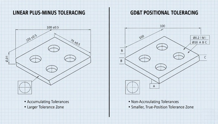
Traditional Tolerancing vs GD&T
Traditional dimensioning controls size but does not fully describe shape or functional relationships. GD&T solves this gap by defining geometric accuracy.
Below is a concise comparison your CNC supplier expects you to understand:
| Method | What It Defines | Limitations | Best Use Case |
|---|---|---|---|
| Traditional Tolerancing | Feature size and linear variation | No control over form, orientation, or true location | Simple, non-critical features |
| GD&T | Form, orientation, location, and profile | Requires engineering understanding | Functional parts, assemblies, precision fits |
GD&T ensures parts fit and function as designed, even when shapes deviate within allowable limits. This makes it essential for precision CNC machining, assemblies, and high-performance components.
What Is GD&T?
Purpose of GD&T in CNC Machining
GD&T is a symbolic engineering language that defines the allowable variation of a part’s geometry. It helps engineers communicate functional requirements clearly so a CNC supplier machines features exactly as intended. The purpose of GD&T is to ensure that parts assemble, align, and perform correctly—even when small variations occur during machining.
GD&T focuses on how a feature must behave in relation to other features, not just its size. This functional approach gives engineers a more precise way to describe flatness, orientation, runout, and positional accuracy. Manufacturers then use these symbols to choose proper tooling, setup methods, and inspection strategies. Without GD&T, suppliers may misinterpret design intent, resulting in increased scrap rates or assembly issues.

How GD&T Solves Limitations of Traditional Tolerancing?
Traditional tolerances only control size. They do not define how two surfaces must interact, how a cylinder must align, or how flat a mating face must be for sealing performance. This lack of geometric clarity often leads to inconsistent assemblies.
GD&T addresses these limitations by:
-
Defining form requirements (flatness, straightness, roundness)
-
Controlling orientation (parallelism, perpendicularity, angularity)
-
Specifying location with higher accuracy (true position, concentricity)
-
Managing profile control for complex surfaces
These symbols allow CNC machinists to understand what matters most. For example, you can permit generous size variation while still enforcing strict positional accuracy. This flexibility often reduces machining cost because suppliers can optimize tool paths without violating functional constraints.

Why Modern Manufacturing Relies on GD&T ?
Modern CNC machining relies on GD&T because global manufacturing requires clear, standardized communication. Two primary standards guide GD&T usage:
-
ASME Y14.5 (widely used in North America)
-
ISO 1101 & ISO GPS standards (widely used in Europe & Asia)
These standards define symbol meaning, how to apply GD&T, and how parts must be inspected. Because CNC machining has become more international, adhering to these standards ensures that:
-
Drawings are interpreted consistently
-
Inspection reports match functional expectations
-
RFQs move faster with fewer clarification rounds
-
Cross-border manufacturing avoids assembly failures
GD&T supports digital workflows as well. CAD tools such as SolidWorks, Creo, and Fusion 360 embed GD&T in PMI annotations, enabling MBD (Model-Based Definition). This reduces drawing ambiguity and improves CNC quoting accuracy.
Core GD&T Elements Every Engineer Must Understand
Datums — The Foundation of CNC Accuracy
A machinist cannot produce or inspect a CNC part reliably unless the datum structure is clear, stable, and logically placed. Datums establish the reference framework that dictates how the part is set up on the machine and how measurement tools evaluate it. Without a good datum scheme, even the most precise tolerance values become meaningless.
A well-designed datum system typically follows a 3-2-1 logic:
-
Primary Datum (plane) — establishes the main contact surface, removing three degrees of freedom.
-
Secondary Datum (plane or axis) — locks rotation, removing two additional degrees of freedom.
-
Tertiary Datum (point or plane) — fixes the final translation, removing the last degree of freedom.
When you choose datum features, your priority should be functional assembly, not simply “what’s easiest to dimension.” For example, if a housing aligns to a motor through a mounting face, that face must become the primary datum—not the largest surface. In CNC machining, poor datum selection often leads to:
-
Parts that fit the CMM but fail in real assemblies
-
Machining setups with unnecessary refixturing
-
Accumulated error due to unstable or curved datum surfaces
-
RFQ delays because suppliers ask for clarification
A strong datum structure reduces ambiguity, supports repeatable machining, and ensures the part’s functional geometry remains consistent across batches and suppliers.
Feature Control Frame — Structure, Symbols & Interpretation
The Feature Control Frame (FCF) is the core instruction block of GD&T. It tells the machinist how a feature must behave, what limits apply, and how compliance will be measured.

An FCF always contains:
-
Geometric characteristic symbol
-
Tolerance value (linear, diametral, or angular)
-
Material condition modifier (if applicable)
-
Datum reference frame (ordered A → B → C)
This frame conveys:
-
The hole must lie within a cylindrical 0.10 mm positional tolerance zone
-
MMC applies, meaning the allowable tolerance increases as the hole departs from its minimum size (bonus tolerance)
-
The position is verified relative to datums A, B, and C in that exact sequence
Understanding an FCF allows engineers to anticipate machining requirements:
-
Does the feature require a 3-axis or 5-axis setup?
-
Does the tolerance demand probing cycles or CMM verification?
-
Will bonus tolerance significantly reduce manufacturing cost?
-
Does the datum order match assembly function?
Poorly structured FCFs are one of the top causes of inaccurate quotes and manufacturing disputes.
Basic Dimensions — Usage & Meaning
Basic dimensions are presented in boxed format on drawings, indicating exact theoretical values the designer expects the feature to target. Unlike traditional tolerancing, basic dimensions carry no tolerance of their own. They rely entirely on the geometric control in the FCF.
Basic dimensions are essential for:
-
Hole patterns (perfect theoretical locations)
-
True position calculations
-
Profile tolerances defining exact form
-
Angles controlled by orientation callouts
-
Datum-to-feature relationships
Engineers should use basic dimensions to describe ideal geometry, but they must avoid mixing basic and non-basic dimensions randomly. A common mistake is placing a basic dimension without a corresponding GD&T frame, leaving machinists unsure how to interpret it.
In CNC practice, machinists use basic dimensions to program exact toolpaths, then use the GD&T tolerance to validate the achieved accuracy. This gives both sides clarity: the designer defines intent, and the machinist controls practical deviation.
Material Condition Modifiers (MMC, LMC, RFS)
Material condition modifiers help balance functional fit and manufacturing cost by defining how tolerances behave as features vary in size.
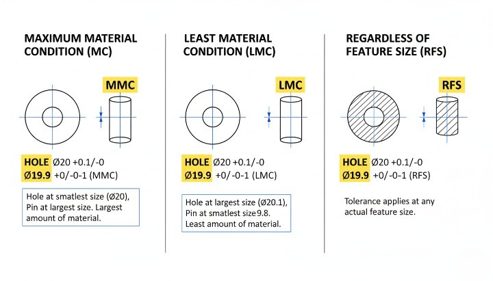
Maximum Material Condition (MMC)
The feature contains the maximum amount of material:
-
Smallest hole
-
Largest pin or boss
MMC allows bonus tolerance, making the part easier to machine without compromising function. Example: A bolt hole defined at MMC ensures the mating bolt always fits even if actual position shifts slightly.
Least Material Condition (LMC)
The feature contains the least amount of material:
-
Largest hole
-
Smallest pin
LMC protects features where material thickness is safety-critical, such as sealing edges, thin walls, or contact pads.
Regardless of Feature Size (RFS)
No matter the feature’s size, the tolerance stays fixed. RFS is used when function requires strict control without trade-offs.
Practical CNC implications:
-
MMC can reduce cost by 20–40% because machinists gain more freedom.
-
LMC prevents structural weakening in load-bearing or thin-wall components.
-
RFS often requires tighter process control and longer cycle time.
Engineers who understand when to use these modifiers can significantly improve both performance and manufacturability.
How Datums, Basic Dimensions & FCF Work Together?
Datums, basic dimensions, and FCFs form an interconnected system. None of them can function effectively in isolation.

Their interaction can be understood as a flow:
-
Datums create the origin and orientation of the measurement system.
-
Basic dimensions define the perfect geometry relative to that datum framework.
-
The FCF specifies how far real machining can deviate from the ideal.
For example: If a bolt hole pattern uses basic dimensions to define the theoretical grid, the FCF ensures each hole stays within the acceptable positional tolerance relative to assembly-critical datums.
When this system is designed correctly:
-
Machining setups become straightforward
-
CMM inspection paths become unambiguous
-
RFQs get quoted faster because the supplier understands the intent
-
Dimensional variation becomes predictable across multiple production batches
When the system is designed poorly:
-
Every supplier interprets the drawing differently
-
CMM vs. functional fit results contradict each other
-
Machinists must guess the design intent
-
Assembly failures appear even if “all features are in tolerance”
A well-constructed GD&T framework is not simply documentation; it is an engineering control system that connects design intent, machining reality, and production consistency.
Complete Guide to GD&T Symbols in CNC Machining
GD&T symbols define how a feature must behave when the part is machined, assembled, and inspected. When you read a CNC machining drawing, your ability to interpret these symbols directly determines how accurately you understand the design intent. Each category of symbols controls a different geometric attribute, and engineers rely on them to manage form, orientation, location, and function. A correct interpretation helps you judge manufacturing feasibility, predict machining time, and avoid RFQ delays caused by unclear requirements.
Form Controls (Flatness, Straightness, Circularity, Cylindricity)
Form controls govern the shape of a feature without referencing a datum. These are the foundation of part geometry because they describe how “true” a surface or feature must be. In CNC machining, form errors often appear due to tool deflection, thermal distortion, or uneven material removal. Form controls help prevent these deviations from affecting assembly or sealing performance.

Form controls include:
-
Flatness — Ensures a surface lies entirely between two parallel planes.
-
Straightness — Controls the straightness of a line element or axis.
-
Circularity (Roundness) — Ensures a circular feature stays equidistant from its center.
-
Cylindricity — Controls the entire cylindrical feature’s shape, including straightness and roundness.
These controls are particularly important when machining mounting plates, sealing flanges, precision shafts, and dowel-pin holes. Flatness and cylindricity often require finishing operations or proper fixturing strategies to ensure stable results.
Orientation Controls (Perpendicularity, Parallelism, Angularity)
Orientation controls dictate how one feature must align relative to another. Unlike form controls, they require datums because they evaluate relationship-driven geometry. CNC machinists use these controls to set up machining orientation, choose the right tools, and determine how many operations the part requires.

The main orientation controls are:
-
Perpendicularity — Keeps surfaces or axes at 90° to a datum.
-
Parallelism — Ensures features maintain constant spacing relative to a datum plane or axis.
-
Angularity — Controls any non-90° angle relative to a datum.
These tolerances affect milling strategies, toolpath orientation, and fixture design. For example, tight perpendicularity on a bore may require reaming or line-boring to meet the specified tolerance. Understanding orientation controls helps both engineers and buyers anticipate machining cost and operational complexity.
Location Controls (Position, Concentricity, Symmetry)
Location controls determine the exact placement of features relative to datums. These are among the most important GD&T symbols in CNC machining because they directly affect assembly fit, alignment, and functional behavior.

Key location controls include:
-
Position — Defines the allowable variation in the location of holes, slots, and bosses.
-
Concentricity — Aligns the median points of two diameters.
-
Symmetry — Ensures a feature lies centered between datum planes.
Positional tolerance is used extensively because it provides a cylindrical tolerance zone, which is more realistic and easier to machine compared to rectangular tolerance blocks. Engineers use positional tolerancing to control bolt patterns, bearing fits, gear locations, and precision mounting features. Incorrect positional callouts are one of the biggest causes of rejected CNC parts, so clear interpretation is essential.
Runout Controls (Circular Runout & Total Runout)
Runout controls manage the combined effects of feature form and location when a part rotates. These are crucial for rotating CNC components such as shafts, hubs, pulleys, and transmission parts.

Runout is divided into:
-
Circular Runout — Evaluates form and axis alignment on a per-revolution basis.
-
Total Runout — Monitors the entire surface for cumulative form variation.
Machinists use runout controls to determine whether a turning operation requires a single setup or multiple re-centering operations. Tighter runout tolerances often need additional inspection steps or precision grinding, which increases cost. Running a tolerance too tight can lead to excessive scrap rates, so engineers should assign runout only where function demands it.
Profile Controls (Profile of a Line, Profile of a Surface)
Profile controls define complex shapes that cannot be captured with simple linear dimensions. These are used extensively in consumer electronics, aerospace housings, injection-molded components, and machined surfaces with aesthetic or aerodynamic requirements.

Two types of profiles exist:
-
Profile of a Line — Controls an individual cross-section.
-
Profile of a Surface — Controls the entire 3D surface envelope.
Profile is one of the most flexible GD&T tools because it can control size, form, orientation, and location in a single symbol. However, poorly applied profile tolerances often create unnecessary machining challenges. Engineers should use profile controls to specify surfaces that truly require controlled geometry rather than using them as general “catch-all” instructions.
Practical CNC Machining Examples for Each Symbol
Understanding symbols in theory is useful, but the real value comes from seeing how they affect machining decisions. The following examples show how common GD&T callouts influence tool selection, machining strategy, and inspection planning.

Examples include:
-
A flange surface requiring flatness may need final face milling with a fly-cutter.
-
A gearbox housing needing strict perpendicularity from bore to mounting face may require a two-operation setup and probing.
-
A shaft requiring cylindricity may need a precision turning pass or post-grind.
-
A bolt pattern controlled by true position determines the accuracy of hole drilling and CMM inspection.
-
A cosmetic surface with profile tolerance may require simultaneous 5-axis contouring or polishing.
These examples help engineers understand how GD&T translates from drawings into actual machining work, allowing them to predict feasibility, cost, and lead time more accurately.
How to Read CNC Machining Drawings Step-by-Step?
Reading CNC machining drawings becomes far easier when you follow a structured approach. Each step builds on the previous one, and this order helps you understand how the part must be machined, inspected, and assembled. When you read a drawing correctly, you reduce the risk of RFQ delays, machining mistakes, and tolerance disputes. The following steps walk you through the process that engineers, machinists, and buyers use every day when evaluating a new part.
Step 1 — Identify Views, Datums & Critical Features
Every drawing starts with views that describe the geometry from different perspectives. You should always begin by identifying the main views, the datums, and any features labeled as critical to function. These elements define how the part must be oriented, measured, and manufactured.

CNC machining drawings typically include front, top, right-side, section views, and detailed views for small features. You will also see highlighted surfaces or features that indicate functional conditions such as sealing faces, alignment areas, and mating interfaces. The datums provide a consistent reference for all tolerances, so identifying datum A, B, and C sets the foundation for interpreting the rest of the drawing. Once you know where the critical surfaces lie, you can evaluate how machining operations must be sequenced.
Step 2 — Decode Dimensions, Limits & Fits
Once you understand the views and datums, the next step is to read the dimensional information. Engineers use linear dimensions, angular dimensions, and tolerance values to define the acceptable variation. These values determine whether a part will fit, function, and assemble properly.

Dimensions may be expressed in limit form (e.g., 10.00–10.05), plus-minus form, or as basic dimensions when GD&T applies. Fit types—such as H7/h6 for interference or clearance fits—explain how mating parts interact. Understanding these dimensions helps you anticipate machining effort because every reduction in tolerance increases machine time. By evaluating dimensions early, you avoid misalignment and assembly failure that arise from improper interpretation.
Step 3 — Interpret Feature Control Frames
After reviewing dimensional tolerances, you should focus on the feature control frames (FCFs). These frames define geometric requirements such as flatness, position, perpendicularity, or profile. Each frame includes a symbol, a tolerance value, and datums that anchor the tolerance zone.

Reading an FCF correctly tells you how to inspect a feature and how much variation is allowed. For example, a positional tolerance might specify exactly how far a hole center can deviate from its ideal location. Understanding these frames is essential because they often control the most functional features of the part. When you know how an FCF applies to a hole, boss, or mounting surface, you can assess machining difficulty and determine whether the tolerance is reasonable for the chosen manufacturing method.
Step 4 — Read Hole Callouts, Threads & Surface Notes
CNC machining drawings rely on detailed hole callouts and thread notes to communicate tool requirements. These callouts may include diameter, depth, angle, thread pitch, countersinks, and counterbores. Ignoring these details often leads to RFQ delays or machining errors.

Thread specifications typically follow ISO or unified standards, and they tell you whether a hole must be tapped or left close-tolerance for assembly. Surface finish notes instruct machinists on the required roughness level, coating, or treatment. Understanding these elements ensures that the part will meet sealing, cosmetic, or mechanical requirements. You also avoid situations where a machinist must request clarification, which slows down your RFQ process.
Step 5 — Validate Assembly Intent & Fit Requirements
A drawing is more than a geometric description—it defines how a part must function within a system. As you read the drawing, identify notes or symbols that reference assembly fit, alignment, or mating surfaces. These requirements often influence the machining plan and the inspection method.

If a part must align with another component, positional tolerances and datums become critical. If it must seal, flatness and surface finish take priority. By confirming assembly intent early, you ensure that the machining approach supports functional outcomes and that tolerances are chosen for engineering reasons rather than guesswork. This step also helps you catch potential over-specification, which may increase manufacturing cost without improving performance.
Step 6 — Check Tolerance Stack-Up
The final step in reading a CNC machining drawing is to evaluate how all tolerances accumulate across the part. Tolerance stack-up determines whether the part will still function after every dimension varies within its allowable range. This analysis is crucial for parts with multiple aligned features such as bolt patterns, bearing seats, and sliding assemblies.

A careful stack-up review prevents costly rework and ensures the supplier understands the true functional limits. When you recognize how individual tolerances interact, you can identify features that require GD&T controls rather than simple linear tolerancing. This helps you confirm that the design is realistic, manufacturable, and ready for RFQ submission.
Reading CNC Drawings for Manufacturability
A CNC drawing tells a supplier what you want, but manufacturability tells them whether it can actually be produced efficiently and accurately. When you read a drawing through a design for CNC machining mindset, you can spot features that drive cost, limit tool access, or increase machining time. The goal is simple: ensure your parts for CNC can be made without unnecessary complexity or risk while keeping quoting fast and accurate.
Features That Increase Machining Cost
Certain design choices increase machining time, tool wear, and fixturing complexity. When engineers understand these factors early, they reduce revisions and speed up the RFQ process.

Tight tolerances, deep pockets, complex surface profiles, and ultra-thin walls often become the biggest obstacles to efficient CNC production. These elements directly influence manufacturability, which is why you must evaluate them carefully before sending prints to any supplier.
• Tight tolerances below ±0.01 mm significantly raise cycle time because the machine must slow down, take multiple passes, and verify measurements often.
• Deep pockets create chip evacuation issues and require long tools, which increases chatter and lowers accuracy.
• Thin walls can vibrate under cutting forces, forcing the machinist to reduce speed.
• Undercuts or micro-features require specialty tooling and often shift the job to a different machining layout.
To ensure DFM analysis accuracy, always ask yourself: “Does this tolerance or feature add functional value, or is it simply inherited from the CAD default?” Removing non-critical precision details is one of the easiest ways to reduce machining cost.
GD&T Requirements That Impact Cycle Time & Tooling
GD&T improves communication, but certain callouts greatly impact machining strategy. Understanding this helps you make cleaner drawings and more predictable RFQs.

Some symbols, such as true position, flatness, and profile, require additional probing, high-precision fixturing, or slower toolpaths—especially on large or thin components.
• Position tolerance requires better fixturing and probing, especially when applied at MMC/LMC.
• Flatness tighter than 0.05 mm often requires face milling plus surface grinding or lapping.
• Surface profile on cosmetic housings forces slow, multi-axis finishing passes.
• Runout controls require perfect spindle alignment, increasing inspection and setup time.
When you apply GD&T, think of it as part of the DFM design for manufacturing process. Every symbol you place on a drawing should improve clarity or guarantee function. If it doesn’t, it may only inflate quote prices.
When Tight Tolerances Are Necessary vs Over-Engineering?
You should use strict tolerances only in areas where parts mate, move, or seal. Over-engineering is one of the most common issues suppliers observe during the DFM process.

Necessary tight tolerances include:
• Bearing bores
• Shaft fits
• Sealing surfaces
• Optical or alignment features
Unnecessary tight tolerances often appear on:
• Non-functional edges
• Aesthetic surfaces
• Slots or holes without mating features
• Uncritical ribs or brackets
An effective design for machining approach is to apply general tolerances (e.g., ISO 2768-m or ASME block tolerances) to the overall drawing, then isolate critical dimensions using GD&T. This keeps cost under control and accelerates quoting.
Common GD&T Misinterpretations That Delay RFQs
RFQ delays often occur because drawings include unclear GD&T, inconsistent notes, or missing definitions. These issues force suppliers to ask follow-up questions before giving an accurate price.

Common mistakes include:
• Using a datum that cannot be physically fixtured
• Applying true position without basic dimensions
• Calling for flatness on flexible parts
• Combining tight tolerances with unstable materials
• Omitting thread depth, chamfers, or hole callout details
• Using GD&T symbols that contradict general tolerances
These errors affect design and manufacturing, causing unnecessary back-and-forth. Clean, consistent drawings signal professionalism and reduce the risk of misinterpretation.
How Suppliers Use GD&T to Select Processes & Fixturing?
CNC machinists rely on your drawing to determine tooling, clamping, order of operations, and inspection strategy. Good GD&T enables them to choose the most efficient machining layout.

Suppliers evaluate:
• How to fixture the part relative to datums
• Whether to use 3-axis, 4-axis, or 5-axis machining
• Which tools and tool lengths are required
• Whether secondary operations (grinding, honing, lapping) are needed
• Which inspection instruments ensure compliance
When your drawing accurately communicates design for CNC machining intent, suppliers can optimize setup and deliver better accuracy at lower cost. Effective DFM analysis bridges the gap between design expectations and machining reality.
CNC Material-Specific GD&T Considerations
Different materials behave very differently under cutting forces, heat, and clamping pressure. When you add GD&T to a drawing, you should always consider how the chosen material responds to tolerances. This mindset is a core part of design for CNC machining, designing for manufacturing, and ensuring real-world manufacturability.
Aluminum — Flatness, Stability & Thin-Wall Behavior
Aluminum is widely used for parts for CNC because it machines quickly and holds tolerance well. But it also flexes easily, which directly affects how GD&T is applied.
Aluminum responds well to most GD&T callouts, but flatness, thin walls, and surface profile requirements must be evaluated through a DFM design lens.

Key considerations:
• Flatness below 0.05 mm can require stress relieving, multiple finishing passes, or even surface grinding on large plates.
• Thin walls (under 1.0–1.5 mm) may warp under clamping pressure or cutting heat.
• Profile tolerances on cosmetic housings require slower toolpaths and may trigger 5-axis finishing.
• True position is stable on short, rigid components but harder to maintain on long frames or brackets.
To ensure manufacturability, engineers should avoid combining tight profile tolerances with long unsupported surfaces. When needed, suppliers often recommend thicker ribs or adding machining reliefs—these come directly from professional DFM analysis.
Stainless Steel — Stress, Warping & Tight Tolerance Challenges
Stainless steel behaves differently from aluminum because it is strong, heat-resistant, and prone to internal stress. It holds tolerances well, but GD&T must respect material behavior.
What engineers must consider:
• Perpendicularity and parallelism are harder to maintain on long stainless parts due to heat buildup.
• Flatness often requires heavy finishing passes and slow feeds.
• Position tolerances on thin stainless flanges may distort when clamped.
• Runout on shafts requires rigid setups and stable tool geometry to avoid heat-induced deviation.
During design for manufacturing, avoid combining extremely tight tolerances (below ±0.01 mm) with long lengths in stainless steel unless functionally necessary. Stainless resists machining, so GD&T that is “too tight” increases cycle time dramatically.
Carbon Steel — Machinability & Reasonable Tolerance Limits
Carbon steel provides good machinability and affordable cost, but some grades have internal stress or hard spots. GD&T must reflect its stable but less predictable behavior.
Important GD&T considerations:
• Straightness can be difficult on long shafts unless stress-relieved stock is used.
• Cylindricity callouts often require precision turning and may need after-machining polishing.
• Profile tolerances depend heavily on tool wear because steel dulls tools quickly.
• Position tolerances hold well on rigid parts but may drift during long run production unless tooling is controlled.
Carbon steel rewards clear GD&T because machinists adjust speeds, tooling, and cooling strategies based on well-defined requirements. This is where DFM design for manufacturability becomes essential.
Copper/Brass — Precision vs Burr Formation
Copper and brass offer excellent machinability, but they create burrs and deform easily under cutting loads. When applying GD&T:
• Avoid extremely tight flatness because soft materials can bow under clamping.
• Use moderate position tolerances; copper deforms more than steel.
• Profile callouts on edges may require deburring or secondary finishing.
• For runout on bushings or sleeves, brass performs very well because it machines cleanly.
If the drawing includes very tight edges or cosmetic requirements, add notes on acceptable burr limits. A supplier will always check these during the DFM process.
Plastics — Thermal Expansion & GD&T Sensitivity
Plastics react dramatically to temperature, moisture, and cutting forces. This makes them the most challenging group for strict GD&T.

Plastics require a different mindset during design for machining:
• Position tolerance looser than metals is normal due to material flexibility.
• Flatness and parallelism may drift as plastic cools after machining.
• Profile tolerances below 0.1 mm are extremely difficult on large surfaces.
• Circularity and cylindricity can vary slightly due to tool heat.
Some plastics expand up to 10× more than aluminum, which makes over-tight GD&T guaranteed to fail inspection. Engineers must design with realistic tolerance zones that match material physics.
Real Engineering Examples — GD&T Done Right vs Wrong
Clear examples help you see how GD&T directly affects design for CNC machining, inspection results, and overall manufacturability. When engineers understand how GD&T interacts with machining forces, fixturing, and thermal behavior, they can avoid rework and speed up the RFQ and production process. Below are practical, real-world scenarios showing correct vs incorrect GD&T application.
Example 1 — True Position on Bolt Patterns

A bolt pattern is one of the most common places where GD&T improves accuracy. When engineers rely only on linear dimensions, small stacking errors can shift hole locations.
Correct Approach (GD&T Applied):
• The drawing defines a center datum structure (A-B-C).
• Holes include a true position tolerance applied to the bolt circle.
• Machinists set up the part relative to the datum scheme, keeping hole alignment consistent.
• Inspection is fast because CMMs read the FCF directly.
Incorrect Approach (Traditional Dimensions Only):
• Each hole uses ± tolerances that accumulate. • Machining layout becomes inconsistent because no datum framework exists. • Assembly fit fails even though all individual holes “meet tolerance.”
Using true position ensures higher functional accuracy, reduces measurement time, and reflects better design for manufacturability.
Example 2 — Flatness Requirements on Large CNC Plates

Large aluminum or steel plates often warp from internal stress or cutting heat. Flatness must be realistic.
Correct GD&T Setup:
• Flatness is specified with a reasonable zone (e.g., 0.1–0.2 mm depending on size).
• The drawing communicates allowable bow and twist.
• Supplier applies multi-step machining and stress-relief techniques.
• RFQ accuracy improves because machinists understand the required steps.
Incorrect Setup:
• Flatness of 0.02 mm is applied to a 300 mm plate without functional justification.
• No notes on stress relief or fixturing.
• Machining becomes expensive or impossible within tolerance.
Proper GD&T avoids unnecessary cost while preserving function — a core part of the DFM process.
Example 3 — Profile Control for Cosmetic Surfaces
Housing surfaces, covers, or industrial design components often require smooth, consistent surfaces.
Correct Use of Profile:
• A profile of surface tolerance defines the global shape requirement.
• Engineers apply a looser range (0.1–0.3 mm) for non-critical faces.
• Machinists choose finishing toolpaths that balance quality and time.
• Inspection teams use CMM scanning instead of patch measurements.
Incorrect Use:
• Overly tight profile tolerances are applied to purely cosmetic surfaces.
• Cost increases without improving product performance.
• Machining time may triple because of unnecessary finishing passes.
Profile is one of the most powerful GD&T controls — but only when paired with good design for machining practices.
Example 4 — Threads & Hole Callouts Using MMC/LMC
Material modifiers dramatically influence inspection and machinability.
Correct GD&T Callout:
• Threaded holes use position at MMC, giving more tolerance when the hole is at maximum size.
• This expands the workable tolerance zone, improving manufacturability.
• Machinists can tap more efficiently without chasing microns.
Incorrect Callout:
• Tight position tolerance (e.g., ⌀0.05 mm) is applied without any material modifier.
• Holes become difficult to inspect and even harder to machine.
• Tool breakage or re-tapping increases production time.
Using MMC or LMC correctly leads to faster, cheaper machining while maintaining assembly fit.
Cost Comparison — Correct vs Over-Toleranced Drawing
Here is a simplified comparison that shows how GD&T decisions affect cost and lead time:
| Drawing Type | Machining Cost Impact | Inspection Time | Manufacturability Result |
|---|---|---|---|
| Correct GD&T | Medium | Fast | Stable and repeatable |
| Over-Toleranced | Very High | Slow | Frequent QC failures |
| Missing/Incorrect GD&T | Medium-High | Medium | Risk of misinterpretation |
Engineers should always connect GD&T decisions to the realities of machining: cutter deflection, clamping, thermal expansion, and multi-axis accessibility. This mindset is central to design for manufacturability and effective RFQ communication.
Digital GD&T: How CAD/CAM Systems Use Tolerances?
Modern manufacturing relies heavily on digital workflows, and understanding how CAD/CAM platforms handle GD&T is essential for accurate quoting, machining strategy, and inspection. When you embed tolerances directly inside your model, you reduce interpretation errors and improve the supplier’s ability to evaluate manufacturability during their DFM analysis.
Digital GD&T also strengthens collaboration between engineering and machining teams. Instead of relying solely on 2D drawings, machinists can access embedded PMI data, feature definitions, and tolerance structures inside the 3D model. This shift dramatically improves clarity and accelerates the entire design for CNC machining workflow.
GD&T in SolidWorks, Fusion 360, Creo

Most leading CAD systems now support integrated GD&T tools that allow you to define datums, feature control frames, and material modifiers directly on the 3D geometry.
These platforms help engineers produce clear, interpretable files for parts for CNC, especially when tolerances affect machining strategy.
Key advantages across platforms:
• SolidWorks supports full DimXpert and MBD workflows, allowing PMI annotations directly on the model.
• Fusion 360 provides intuitive GD&T tools combined with CAM, allowing machinists to adjust toolpaths based on tolerances.
• Creo offers robust enterprise-grade GD&T with semantic PMI, ensuring consistent interpretation across PLM systems.
In each of these platforms, engineers can move beyond static 2D drawings toward smart models that communicate intent more precisely. This directly improves designing for manufacturing and reduces quoting mistakes.
Benefits of PMI (Product Manufacturing Information)
PMI transforms your CAD model into a complete manufacturing definition, eliminating ambiguity often found in 2D drawings. PMI typically includes:
• GD&T tolerance frames
• Datum feature definitions
• Surface finish requirements
• Hole callouts, threads, and tolerancing schemes
• Material and process notes
PMI provides a structured, machine-readable format that downstream systems—including CAM and CMM—can read.
This improves:
• RFQ accuracy
• Toolpath optimization
• Fixturing and machining layout decisions
• Digital inspection programming
PMI also prevents errors that occur when a supplier misreads a drawing, which is common in international supply chains.
How Digital GD&T Improves RFQ Accuracy?
Digital GD&T gives suppliers a more complete dataset, letting them evaluate the entire part with fewer assumptions. This clarity reduces delays during quoting and eliminates unnecessary back-and-forth.
Specific RFQ benefits:
• Suppliers understand tolerance priorities and critical features instantly.
• Machinists can determine whether 3-axis, 4-axis, or 5-axis machining is needed.
• CAM programmers adjust stepovers, tool radii, and roughing strategies based on true position and profile tolerances.
• QC teams can pre-plan inspection fixtures and CMM routines.
A well-prepared digital file also supports automated DFM process tools used by advanced machine shops, which scan the model to detect undercuts, thin walls, or inaccessible features.
The result is a faster, more accurate quote—and fewer surprises once machining begins.
Preparing CNC Drawings for RFQ Submission
Sending a clear and complete drawing package is one of the most effective ways to speed up quoting, reduce manufacturing risk, and avoid unnecessary email exchanges. Many RFQ delays happen not because the part is difficult, but because the supplier lacks the information needed to evaluate manufacturability, machining strategy, or tolerance impact. A well-prepared RFQ communicates design intent, required tolerances, and functional priorities—allowing machining teams to perform accurate DFM analysis from the start.
Required File Formats (STEP, PDF, DXF, PMI Models)
Suppliers rely on multiple file types to understand geometry, tolerances, and intent. Each file plays a different role in the design for CNC machining workflow.

Essential files to include:
• STEP — The universal format for 3D geometry. Used for CAM programming and machinability checks.
• PDF Engineering Drawing — Shows dimensions, GD&T, surface finish, notes, and inspection requirements.
• DXF — Useful for 2D profiles, laser-cut features, flat patterns, or inspection references.
• PMI-Enabled 3D Model — Ideal when your CAD system supports embedded GD&T. Greatly improves communication clarity.
Best practice: Always send both 3D and 2D. STEP alone is never enough for tolerances, and PDF alone is never enough for machining layout or feature accessibility.
Material & Surface Treatment Specifications
Suppliers must know exactly what material grade and finish you require so they can quote accurately and determine the level of precision needed. Missing or vague specifications cause major RFQ delays.
Include:
• Exact material grade (e.g., 6061-T6, 316, 17-4PH, C360 Brass, POM-C)
• ASTM/ISO standards when applicable
• Surface finish (Ra value or process name: anodizing, powder coating, polishing, etc.)
• Color, gloss, and texture requirements
• Notes that affect secondary machining (masking, threads after anodizing, etc.)
Explain any functional requirements so suppliers can align machining strategies with your design for manufacturability goals.
Quantity, Delivery Timeline & Inspection Requirements
A supplier cannot provide an accurate quote without knowing project expectations. These details influence machine selection, cycle time, fixturing, material sourcing, and QC planning.
Provide:
• Required quantities (prototype, pilot run, mass production)
• Expected delivery timeline
• Shipping requirements or delivery milestones
• Quality levels (first article inspection, PPAP, full CMM report, RoHS/REACH compliance)
• Packaging requirements (individual bagging, protective foam, anti-corrosion treatment)
Quantities directly shape pricing: a part quoted for 10 pcs will have different setup assumptions than a part quoted for 5,000 pcs.
Packaging, Assembly or Secondary Processes
If your part needs more than basic machining, your RFQ should clearly define expectations. Missing these details causes major surprises in cost and timing after production begins.
Include details such as:
• Heat treatment (T6, HRC requirements, nitriding, etc.)
• Assembly steps (press-fitting, bearing installation, multi-part alignment)
• Surface treatments before or after machining
• Welding or bonding
• Thread inserts, helicoils, or special hardware
• Testing or certification needs
These steps can increase complexity, and the supplier will evaluate manufacturability based on the entire workflow—not only the machining portion.
Example of a Well-Prepared CNC RFQ Drawing Package

A strong RFQ package typically includes the following:
| File / Info Type | Purpose | Why It Matters for Manufacturability |
|---|---|---|
| STEP File | 3D geometry | Identifies undercuts, tool access, machining layout |
| PDF Drawing | Dimensions, GD&T, finish | Communicates final functional intent |
| DXF File | 2D outlines | Helps with inspection or secondary ops |
| Material Specification | Grade & standard | Determines speed, tooling, cost |
| Surface Treatment | Finish & protection | Affects final tolerances & cosmetics |
| Qty & Timeline | Production planning | Enables accurate cycle time estimation |
| QC Requirements | CMM, FAIs, reports | Influences inspection cost & method |
A supplier reviewing this package can perform DFM analysis quickly and provide a reliable quote without guesswork or delay.
FAQs About Reading CNC Machining Drawings & GD&T
Clear and accurate drawings are essential to CNC machining, and many engineers—especially those early in their career—ask similar questions when working with GD&T. These FAQs address the most common concerns and help you apply design for CNC machining, design for machining, and practical design for manufacturability principles more confidently.

Why GD&T Matters for CNC Accuracy?
GD&T matters because it defines the functional relationship between features more precisely than traditional tolerances. The machinist uses GD&T to decide how to fixture a part, how to plan toolpaths, and what measurement methods to use during inspection.
When GD&T is missing or incomplete:
• Machinists may choose different datum setups.
• Features may align incorrectly even when sizes look “correct.”
• Assembly issues appear due to tolerance stacking.
GD&T gives suppliers the information they need to machine the part as intended—not just “within size,” but within functional limits. This is critical for parts for CNC that involve alignment, motion, sealing, or structural performance.
How Beginners Can Learn GD&T?
Learning GD&T requires time and practice, but engineers can accelerate their understanding through structured steps:
• Start with the 14 fundamental GD&T symbols and their meaning.
• Learn how feature control frames connect symbols, tolerance zones, and datums.
• Study real drawings from suppliers to understand practical usage.
• Practice reading and interpreting datum structures on simple parts before moving to assemblies.
Beginners often find it helpful to compare GD&T vs traditional tolerances on the same drawing. This strengthens intuition for designing for manufacturing and understanding how suppliers evaluate manufacturability.
Which GD&T Symbols Increase Cost Most?
Some GD&T symbols significantly influence machining time, toolpath strategies, and inspection methods. The most cost-impacting are:
• True Position — especially on tight tolerance bolt patterns.
• Flatness — when applied to large surfaces or thin plates.
• Profile of a Surface — because it affects entire geometry, not isolated features.
• Total Runout — requiring high-precision turning, inspection, and fixturing.
When engineers use these symbols, the supplier must adjust speeds, feeds, tool geometry, or even the entire machining layout. This is why GD&T applied without functional justification increases cost.
Do All CNC Drawings Need GD&T?
Not all CNC drawings need GD&T, but many benefit from it.
GD&T is essential when:
• Features must align accurately across multiple surfaces.
• Parts fit into assemblies with directional or positional requirements.
• Holes or slots must match mating components.
• Cosmetic surfaces require controlled profile.
• Components experience dynamic loads or motion.
GD&T may be unnecessary when:
• Fit is non-critical.
• Only basic size and location matter.
• Parts are prototypes with low functional demands.
A good rule is: Use GD&T when functional quality depends on more than linear dimensioning.
Positional Tolerance vs Linear Tolerance
Positional tolerance and linear tolerance may appear similar, but they control completely different outcomes.
Linear Tolerance:
• Controls only X/Y or length variation.
• Does not guarantee rotational or angular alignment.
• Allows tolerance stacking that affects assembly.
Positional Tolerance (True Position):
• Controls the exact 3D location of a feature relative to datums.
• Adds functional accuracy to holes and critical features.
• Removes ambiguity in how machinists and inspectors measure the part.
Engineers who rely only on linear tolerances miss the geometric relationships that matter most in real assemblies. This is why positional tolerancing is central to modern design for manufacturability and the broader DFM process.
Conclusion
Understanding how to read CNC machining drawings—and especially how to apply GD&T correctly—gives you a major advantage when moving a design from concept to production. When you interpret datums, feature control frames, material modifiers, and tolerance zones with confidence, you reduce risk, prevent miscommunication, and help suppliers calculate accurate quotes on the first attempt. Clear drawings also support stronger design for CNC machining practices and improve overall manufacturability, because machinists can quickly understand which features matter most and which tolerances drive functional performance.
Engineers who master drawing interpretation avoid the common traps that delay RFQs or increase machining cost. Whether you’re reviewing bolt patterns, controlling flatness on large plates, defining profile tolerances, or selecting realistic tolerances for plastics and metals, the principles of GD&T help you communicate engineering intent without ambiguity. This knowledge improves collaboration with suppliers and leads to more predictable results across prototypes, pre-production, and full-scale manufacturing.
Need Help Interpreting CNC Drawings? Get a Free GD&T Review
If you want expert support reviewing your CNC drawings before sending an RFQ, our engineering team can help. We provide free drawing assessments, GD&T checks, and DFM analysis to ensure your design is fully manufacturable before it reaches the machine. You can also send us your STEP files, PDFs, and tolerance requirements—we’ll help you identify risk areas, cost drivers, and opportunities for improvement.
If you’re preparing new parts for CNC, or you want to verify that your current drawings follow strong design for manufacturability