


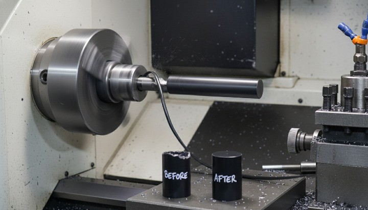
Machining TPU parts looks simple until the material starts moving during CNC machining. TPU is flexible, elastic, and heat sensitive, so it behaves less like a rigid plastic and more like a springy system in thermoplastic polyurethane cutting.
Clamp it like aluminum and it distorts. Cut it like ABS and it smears, especially in CNC milling and CNC turning where heat and rubbing cause tool loading. Measure it like steel and your reading can reflect measurement force more than true geometry.
This guide fills that gap with a practical playbook for CNC machining TPU parts. You will learn when CNC makes sense, what Shore A hardness to specify, and how cooling, tooling, and workholding drive results. You will also get a decision tree, a six step checklist, a troubleshooting table, a post processing section, and an RFQ checklist you can copy into your sourcing workflow.
Can you machine TPU?
Yes, you can CNC machine TPU, but only if you treat it like a flexible system. If you machine TPU like a rigid block, you will often see distortion, fuzzy edges, and dimension drift after unclamping.
At HM we make TPU machining repeatable by doing three things consistently.
-
We stiffen TPU during cutting using cold air and when needed liquid nitrogen
-
We use extremely sharp high rake tools and avoid coated tools that tend to stick
-
We hold parts without squeeze distortion using vacuum fixtures or strong double sided tape
There is also one rule that prevents wasted iterations. CNC machining is most stable on Shore 90A and 95A hard TPU. If your requirement is below Shore 80A, vacuum casting is often the faster and more reliable option.
Six step method for stable TPU CNC machining
Use this checklist to evaluate a supplier or to plan builds that repeat.
-
Confirm Shore hardness and application environment before quoting
-
Choose workholding that supports the part without squeezing it
-
Select sharp high rake tools and keep tool condition fresh
-
Add cooling at the cutting zone using cold air and consider liquid nitrogen when needed
-
Use toolpaths that avoid dwell and keep engagement stable
-
Inspect with low force methods and define acceptance on functional CTQs
If a shop cannot explain these six steps in practical terms, expect either a widened tolerance recommendation or inconsistent parts.
What TPU is and what matters for machining?
TPU is part of the polyurethane family of polymers, which includes materials used as plastics, foams, resins, and elastomers. () For machining, the most important takeaway is not the chemistry. It is behavior.
TPU brings three behaviors that drive most machining failures.
-
Elastic deflection under clamp force and cutting force
-
Spring back after unclamping and after roughing passes
-
Heat driven smearing when the tool rubs instead of shearing chips
These behaviors explain why two suppliers can machine the same CAD and deliver different fits. The difference is rarely the CAD. It is how much the TPU moved during the cut and how heat was controlled.
Material selection that improves CNC success
Material choice drives machining stability more than most teams expect. Specify Shore A hardness and the application environment in the RFQ, then align grade selection with wear, oils, and flex cycles to avoid “same CAD, different behavior.” If you need a quick shortlisting framework, start from our materials guidance and validate with one controlled prototype.
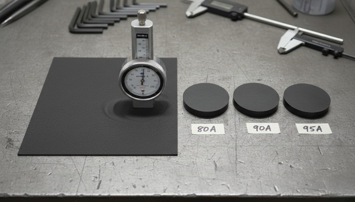
Shore hardness is a process control input
Shore hardness is commonly specified using durometer methods defined in standards. ASTM D2240 describes durometer hardness measurement across multiple durometer types and materials including thermoplastic elastomers. () ISO 868 specifies indentation hardness measurement of plastics using Shore durometers and distinguishes Type A for softer materials and Type D for harder materials.
If hardness is missing, suppliers may choose different grades that meet a vague “TPU” callout but machine and perform differently.
Choose a grade that matches environment and life cycle
Hardness alone is not the full story. Oils, abrasion, temperature cycles, and repeated flexing can change which TPU grade makes sense. If you do not know the grade yet, describe function and environment so your supplier can propose options rather than guessing.
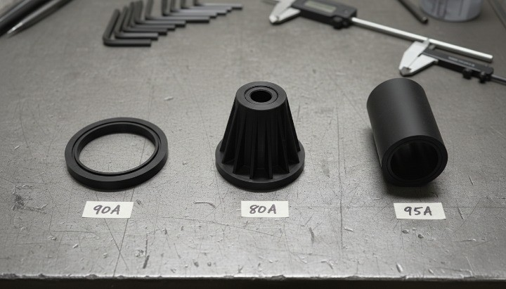
Hardness decision tree for CNC machining TPU
Use this short decision tree as an RFQ rule.
-
Shore 95A and 90A hard TPU is the best fit for CNC machining
-
Shore 80A to 90A can be machined but geometry and support drive yield
-
Below Shore 80A consider vacuum casting as the default option
This is not a limitation statement. It is a cost and risk control statement. It protects you from chasing tight tolerances on a material that behaves like rubber at room temperature.
When to CNC machine TPU and when to switch processes?
TPU can be machined, printed, molded, or cast. The fastest path depends on what matters most.
When CNC machining TPU is the right choice
Choose CNC when you need tight tolerances, clean sealing lands, or crisp mating faces on rubber-like TPU. In practice, turned grooves, sleeves, and circular features benefit most because CNC turning controls geometry well—see our CNC turning parts service for typical outcomes.
CNC is often best when you need one or more of the following.
-
Tight functional interfaces such as grooves seats and mating faces
-
Clean edge definition on sealing lands
-
Low volume prototypes or bridge production where mold tooling cost does not make sense
-
Controlled fit behavior where additive variability is a risk
CNC is also useful when you need fast iteration with predictable CTQs, especially on hard TPU.
When 3D printing is the better option
Additive methods are attractive when:
-
geometry is complex and difficult to fixture
-
internal structures or compliant lattices are important
-
surface texture is acceptable and tolerance demands are moderate
For many teams, printing is a speed tool. CNC is a precision tool. Choose accordingly.
When injection molding is the better option
Molding tends to win when:
-
volume is high
-
part to part free state geometry must be consistent
-
you can design for molding with draft and controlled wall transitions
Molding becomes attractive when volume justifies mold cost and process tuning.
When vacuum casting is the better option
Vacuum casting becomes attractive when:
-
your TPU requirement is very soft and rubber like
-
below Shore 80A behavior is critical
-
free state shape stability matters more than machined interfaces
It is often the quickest way to get soft parts that behave consistently without chasing aggressive CNC setups.
Why machining TPU fails in production?
TPU machining problems usually come from a few predictable root causes. Understanding them makes fixes faster.
Distortion from clamping and cutting forces
TPU compresses under clamp force. It bends under cutting force. If you machine while the part is distorted, it springs back after unclamping and the finished dimension changes. This is why workholding is the number one lever.
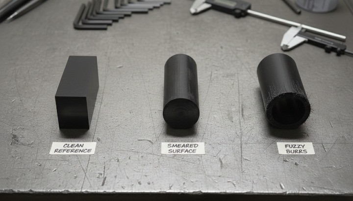
Heat smearing and tool loading
TPU smears when the tool rubs and heats the surface rather than shearing chips. Smearing loads the cutting edge with gummy material, which then worsens finish and size control.
Triggers include dull tools, wrong geometry, dwell in the cut, chip recutting, and overly light cuts that polish rather than cut.
Edge tearing fuzzy burrs and weak interfaces
TPU can create stringy burrs and fuzzy edges, especially on unsupported thin features. Burrs are not only cosmetic. They change fit and sealing behavior and can break off later.
Dimensional drift and inspection error
TPU can relax after machining, especially if it was squeezed during clamping. Measurement can also deform the part. If inspection conditions are not defined, teams argue about the gauge rather than the process.
The HM playbook for CNC machining TPU
Generic TPU articles stop at material properties. The ranking opportunity is explaining CNC reality. HM focuses on three levers that make TPU machining repeatable. When these are controlled, feeds and speeds become tuning rather than guessing.
Cooling and freezing to stiffen TPU during cutting
At room temperature TPU can be too soft. Turning and milling may feel like cutting a soft eraser. The material bends away from the edge, grabs the cutter, and tears instead of shearing.
The most effective correction is increasing stiffness during the cut.

Cold air guns for TPU machining
HM uses cold air guns aimed at the cutting zone to reduce heat driven smearing and to stiffen TPU. Cold air is often enough to shift cutting from rubbing to shearing, especially on hard TPU grades.
Liquid nitrogen for demanding tolerance and edge control
For challenging jobs HM can use liquid nitrogen to drive TPU colder and stiffer at the cutting interface. This is not a gimmick. It is a process control lever used when you need crisp edges and stable dimensions on difficult geometry.
Liquid nitrogen use also requires safety controls. OSHA hazard alerts describe how nitrogen releases can displace oxygen in work areas and create severe asphyxiation risk, which is why ventilation and monitoring matter. ()
Why cooling improves tolerance and edge quality?
Cooling can:
-
reduce smearing and gummy chip formation
-
increase stiffness and reduce deflection at the cut
-
improve edge definition and repeatability
-
reduce tool loading and sudden quality drift
Practical notes for buyers
Cooling introduces cleanliness and handling considerations. Condensation and icing can occur. If your part has bonding adhesive or high cleanliness requirements, call that out during RFQ so the cooling and cleaning plan matches your application.
Tooling that works on TPU and what to avoid
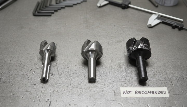
TPU punishes the wrong tool choice.
Use sharp high rake aluminum style tools
TPU needs a slicing action. HM prefers high rake tools with extremely sharp edges. Polished flutes can help chip flow and reduce sticking. Sharpness is the first priority. A dull edge rubs, heat rises, and smearing begins.
Avoid coated tools
Coated tools are common for metal cutting, but TPU behaves differently. Coatings can promote sticking and built up material in gummy elastomers, especially when the cut transitions into rubbing. HM typically avoids coated tools for TPU and prioritizes sharpness and geometry instead.
Toolpath rules that keep TPU stable
TPU often fails when the tool pauses and heats a localized area. Practical rules that help:
-
avoid dwell and pauses in contact with the surface
-
keep engagement consistent where possible
-
use smooth linking moves
-
keep tool stickout short
-
plan finishing passes that do not re enter edges aggressively
If finish changes halfway down a wall, look for a dwell segment or a corner that changed engagement and heat.
Workholding that prevents distortion and prevents ejection
TPU creates a workholding trap. Clamp hard and it deforms. Clamp lightly and it can shift.
Why vise clamping often fails?
A vise squeezes. TPU compresses. That compression shifts datums and changes geometry. After unclamping, spring back changes size and the part may fail assembly even if it measured well while squeezed.
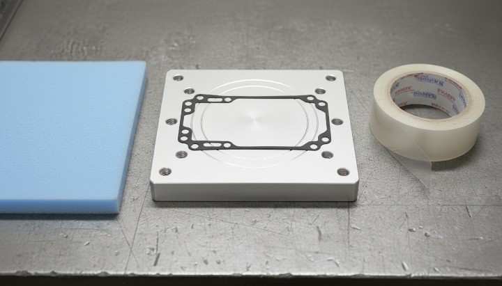
Vacuum fixtures and double sided tape
HM often uses vacuum fixtures or strong double sided tape instead of vise clamping.
Vacuum distributes holding force and reduces local squeeze distortion. Tape holds thin parts without clamp deformation and supports edge quality, especially for small or thin components.
Support methods that raise success rate
Support is the hidden key to crisp edges.
A high success method is sandwich machining.
-
Place TPU between sacrificial plates or between a plate and a nest
-
Expose only the region that needs cutting
-
Use the backing to prevent tear out and stabilize edges
If you see fuzz and tearing, treat it as a support problem first. Add a keeper plate backing tabs or temporary bridges so the feature does not behave like a free spring during the cut.
Feature specific machining tactics
TPU issues are feature dependent. These are the areas where scrap usually concentrates.
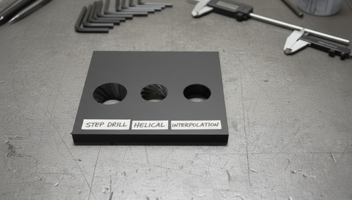
Holes and bores
Holes in TPU can grab tools and distort. Strategies that improve results:
-
pilot drilling or step drilling to reduce pull in
-
sharp drills intended for plastics
-
strong support under the drilling zone
-
boring or interpolation for tight hole requirements
Reaming can rub and generate heat. For tight holes, boring with support is often more stable.
Threads and inserts
Threads cut directly into TPU can strip over time, especially in softer grades or thin walls. For long term reliability consider threaded inserts or rigid interface features. If you must cut threads, use robust walls and validate torque and pull out on prototypes.
Sealing faces and grooves
If the part seals, edge quality and local flatness matter more than general finish. Support the sealing land during finishing, avoid tearing at groove edges, and verify with a functional seal check rather than relying only on a dimensional report.
Post processing and edge quality for TPU parts
Many teams underestimate post processing because TPU feels soft. In practice, post processing is where you protect the functional edges that drive sealing and fit.
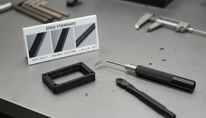
Deburring that does not tear edges
TPU burrs can be stringy. Aggressive mechanical deburring can tear edges and change geometry. A better approach is to control burr formation first using support and sharp tools, then remove minimal material during cleanup.
For critical sealing lands, define an edge condition such as no loose strings and accept small radii only if function allows. A photo based edge standard is often more useful than a generic “deburr all edges” note.
Cleaning and handling for flexible surfaces
TPU surfaces can pick up dust and lint, especially after machining with tape or when cooled. If the part will be bonded or sealed, specify cleanliness requirements and packaging early so the shop can match the process to your downstream needs.
Tolerances and inspection for flexible TPU parts
For TPU machining tolerances, inspection method is part of the tolerance, because contact force can compress the part and shift readings. Define CTQs, define the measurement condition, and use low-force gauges or fixtures so you measure geometry, not deflection. Our quality control process focuses on repeatability, not “one-time pass” reports.
How to specify tolerances without over constraining?
Start from function.
-
which surfaces seal
-
which surfaces locate assembly
-
which dimensions control interference gap or force
Apply tight tolerances only to CTQs. Leave non critical geometry with wider tolerance to stabilize yield and reduce cost. If a feature is sensitive to compression, define inspection condition such as free state or in fixture.
How to measure without deforming the part?
Measurement succeeds when you reduce contact force and increase repeatability.
-
use go no go gauges for fits
-
use fixture based inspection for soft thin features
-
allow relaxation time after unclamping before final measurement
-
define a gentle method if calipers are used
The goal is to measure the part, not the compression you applied.
First article inspection that prevents surprises
For TPU, include functional checks beyond dimensions:
-
fit check in the mating assembly
-
seal compression or leak check when applicable
-
photo based edge quality standard for fuzz tearing and tool marks
Troubleshooting table symptom cause fix alternative
| Symptom | Likely cause | CNC fix | Better alternative |
|---|---|---|---|
| Smearing melted look | rubbing heat dwell dull tool | sharp high rake tool avoid dwell improve chip evacuation add cold air or liquid nitrogen | molding for volume printing for non critical |
| Fuzzy edges stringy burrs | unsupported edge tearing | sandwich backing vacuum or tape support sharp tool stable finish pass | die cutting for flat parts molding for repeat edges |
| Size changes after unclamp | clamp distortion spring back | vacuum or nest lower clamp pressure rough rest finish keep supported | molding for stable free state |
| Holes oval oversized | tool grab flex heat | support under hole step drilling interpolate or bore avoid aggressive ream | molding or insert molding |
| Part lifts chatters | high side force | lower radial engagement smoother toolpath keeper plate shorter stickout | printing for complex shapes |
RFQ checklist for accurate TPU machining quotes
A good RFQ prevents quote swings and reduces rework. Share CAD, target Shore A hardness, quantity, environment, and CTQs, then ask for a machining plan that addresses cold air cooling, optional liquid nitrogen for stiffness, and distortion-free workholding such as a vacuum fixture. Our R&D and engineering support helps you lock assumptions before cutting starts.
Material information to include
-
TPU grade if known
-
Shore hardness requirement using recognized methods such as ASTM D2240 or ISO 868 environment such as water oils temperature UV
-
cleanliness and cosmetic requirements
Functional requirements to include
-
sealing and compression behavior
-
abrasion and wear needs
-
cycle life expectations
Drawing notes to include
-
mark CTQs and functional interfaces
-
identify thin walls and spring features
-
define inspection expectations for soft zones
-
include quantity and target lead time
When you share the assembly context and what failure looks like, you shorten quoting cycles and improve first pass success.
Conclusion
You want TPU parts that hold tolerances, keep clean edges, and fit the first time. The fastest way is a machining plan built for flexible materials—clear Shore hardness, distortion free workholding, sharp high rake tooling, and cooling options when needed—plus an inspection method that does not compress the part.
Contact us today to upload your CAD and requirements. We will review manufacturability, recommend the best process, and send a fast quote.
FAQ
What hardness is best for CNC machining TPU?
Hard TPU around Shore 90A and 95A is the most predictable. Below Shore 80A, vacuum casting is often a better default.
Why does TPU smear during machining?
Smearing happens when the tool rubs and heats the surface. Sharp high rake tools stable engagement strong chip evacuation and cooling typically solve it.
Why do dimensions change after unclamping?
TPU springs back after being squeezed or loaded. Use vacuum or tape workholding distribute support and sequence rough rest finish to reduce drift.
Is it better to print TPU parts?
Printing is excellent for complex shapes without fixtures. CNC machining is better for controlled interfaces sealing lands and tighter functional fits.
Are coated tools good for TPU?
Usually not. Coated tools can promote sticking in gummy TPU. Sharp uncoated high rake tools are often safer.
Use vacuum fixtures tape nests soft jaws and sandwich plates. Avoid point clamping in a vise when possible.
Can cooling improve TPU machining?
Yes. Cooling stiffens TPU and reduces smearing. Cold air is often enough, and liquid nitrogen can be used when tighter tolerance and edge definition are required. OSHA hazard alerts explain why oxygen displacement risk must be managed in nitrogen release scenarios.
When should I choose vacuum casting?
Choose vacuum casting when you need very soft behavior below Shore 80A or when free state shape stability is more important than machined interfaces.